Heinz Schumann
University of Education (PH) Weingarten, Germany
For the Design of a Computer integrating
Geometry curriculum
The present state of educational software development does have some standardized products, mostly for plane geometry: Dynamic Geometry Systems. These systems represent a common core curriculum for (middle) secondary geometry independent of specific cultural influences and different styles of interaction; corresponding systems for spatial software are yet less developed. These systems could be considered as a base for a worldwide standard for basic geometric contents and methods, which is available by internet and could be communicatively developed on this platform.
0 DEFICIENCIES OF THE TRADITIONAL geometric TOOLS
The traditional tools: compasses, straightedge, set square, rule protractor, paper and pencil and pocket computer as tools of exploration and reconstruction determine largely the usual way of acquiring elementary geometry at school.
|
Means of exploration |
|
|
Means of reconstruction |
The traditional construction, calculation and visualization tools show marked deficiencies as means of exploring and reconstructing elementary geometry by the student. Such deficiencies of general kind are:
a lack of support of
-
epistemic behavior
-
individualized learning
-
economic working
-
visualization
-
the formation of flexible and functional thinking
-
the development and application of intellectual techniques and heuristic strategies
-
modeling real world etc.
By using adequate graphics systems, these deficiencies can be compensated. The use of such graphics systems however can only complete and not replace the traditional tools, because
-
ultimately the importance of handling the traditional analogue tools for the tactile acquisition of fundamental knowledge in geometry cannot be assessed (an experiment where the effects of learning geometry only by means of the computer are explored, is not acceptable for humanitarian reasons)
-
working with the traditional tools of construction and of measuring is a cultural technique that is not only very important in the mathematical-historical context;
-
the definition of constructive modules with the computer is based essentially on constructive relations as they appear on constructing with the straightedge and the compasses
-
there is a risk that only those geometrical subjects are chosen that are especially adequate for being presented and developed with the computer (which is, of cours,e. also true for the traditional tools in geometry teaching and learning)
-
the continuity of specific curricula has to be guaranteed
-
the amount of media required in the form of hard and software causes considerable problems (for example the students require the necessary hard and software tools to be able to do their homework)
-
a worldwide non-verbal communication standard is inherent in these simple tools
-
the analogue tools are indispensable for tactile application (do-it-yourself activities etc.).
1 DYNAMIC GEOMETRY SYSTEMS FOR PLANE GEOMETRY
1.1 FACILITIES OF GEOMETRIC COMPUTER SYSTEMS
An interactive graphics system that is considered to be suitable for geometrical construction and calculation in global teaching and learning has to meet some geometrical, organizational and general educational facilities.
1.1.1 GEOMETRIC FACILITIES
Generating geometric configurations
The following types of generating geometrical configurations are possible:
(1) The indirect or passive generation by designing procedures with a graphics programming system or a platform independant script language; the input variables are the determining pieces of construction. We get a formal model of the geometrical construction process like the traditional description of the construction written in a normalized language. The configuration is represented by a program. The procedure called up with actualized parameters produces an corresponding example of the configuration as screen drawing.
(
2) The direct or active generation with a graphics system step by step alternately by input of specified commands or options by the user and execution by the system (interactive construction). Two types of graphics systems for interactive construction can be distinguished:
(2a) the command-driven systems
(2b) the menu-controlled systems.
The result of interactive construction is in both cases the target configuration of geometrical construction as a screen drawing.
The systems like (1) can completely describe a configuration using all the control structures for automatic repetition and selection, while by systems of kind (2) only sequential construction algorithms could be executed. The application of the system types (1) and (2a) requires that all the graphical objects to be designed should be named to be able to take reference to them; operation is made with the keyboard and requires the usual command of the semantic and syntax rules of a formal language as in any programming language. Such systems support mainly a graphic handling of constructive elementary geometry aiming at an objective and standardized description of construction. These kinds of representation does not favour selfcorrection by the student, but they are very conducive for learning to plan and to anticipatively imaginate the drawing.
The menu-controlled systems (2b) meet also the demands of a "naive user" who uses such tools only occasionally. Menu-driven graphics systems - where direct access to the graphic objects by the user is possible by means of direct manipulation is guaranteed - support a mainly spontaneous approach to elementary geometry which aims at an individual acquisition and exploration. An interactive construction protocol can be issued. There is an option for repetition of construction processes.
The gap between configuration and drawing of a configuration is widely closed by the installation of drag mode, which does allow easily to represent a configuration by a large variety of isomorphic screen drawings.
Figure generation by direct interaction
Construction processes traditionally carried out with compasses and ruler
In order to carry out construction processes traditionally realized with compasses and ruler the graphics system must be able to refer to and to generate the following elementary graphical objects:
-
points
-
straight lines
-
circles around a center and through a peripheral point
-
point(s) of intersection of straight lines, straight line and circle. and of circles
-
points on straight lines and circles.
(If this facility is met, the "method of geometric loci" for construction problems to be solved with compass and ruler can be realized.)
But the mere simulation of compass. roler and set square construction problems by means of the interactive tool computer in geometry teaching is not sufficient to justify this kind of computer application. Further facilities must offer new possibilities of learning geometry and to compensate the deficiencies of the traditional tools.
More basic figures to be generated
In order to be able to represent more general plane shapes the graphics system must be able to generate the following other elementary graphical objects:
-
half-lines or rays
-
angles (of different kind)
-
polygons
-
arcs of circles
-
conics
and the variety of geometric loci to be individually constructed as referencable objects.
Generation of complex figures
The generation of complex figures derived from basic ones is economically supported by the concept of already implemented or definable macro-construction:
- construction of a perpendicular bisector
- bisection of a straight line segment (i.e. construction of midpoint)
- bisection of an angle (i.e. construction of a line bisecting an angle)
- erection of a perpendicular on a line
- dropping of a perpendicular from a point to a line
- construction of a parallel line
- copying a line segment (replicating a length)
- copying an angle (replicating an angle)
Modification of configurations
Given or constructed figures can be modified regarding their position,orientation, size and appearance preserving or changing their incidential structure.
Modification by dragging
Transformations performed by drag-mode are straight line- and circle- invariant. The following relations (if constructively defined within figures) are generally invariant during drag-mode transformations:
-
parallelism
-
orthogonality
-
part-proportionality (i.e. ratio of lengths)
-
point symmetry (rotational)
-
line symmetry (reflective)
-
incidence (in general).
Geometry of drag-mode could be described as a hybrid from aquiformal and affine geometry.
Modification by mapping
Generating figures by application of mappings like congruencies and similiarities as compositions of elementary mappings preserving certain figure proporties.
Modification by redefining
Redefinition of objects serves the change of figure structur for economical construction and investgation, specifying and generalising figures.
Measurement and calculation of configurations
Besides construction of figures a main topic in elementary geometry is measuring and calculating of figures.
Measurement
The following basic measurements, which have to be compatible to drag mode, are indispensible: measurement of
-
distances (in relation to a relative length unit as a function of the screen)
-
line segments
-
arcs
-
perimeters of polygons and circles
-
angles (of different kind)
-
area of polygons and circles
Measurements can be gathered in tables. The input of given measurements is possible. The givens of construction problems can be measurements of angles and line segments. The student uses the measures of line segments or angles for marking off line segments and for laying off angles.
Calculation
From measurements can be derived calculations by generation of terms.
Calculated data can be gathered in tables.
The values of that tems depending on figure variation by drag-mode.
Macro-calculation
Analoguely to the concept of macro construction there can be defined macro calculations with quantitative variables.
Interface for coordinate geometry
There is the possibility of embedding synthetic geometric configurations into a coordinate system and to issue point coordinates and equations of basic graphical objects like straight lines and conics.
Editing of figures
There are editing possibilities for reversable hiding auxiliary objects, for appearance (kind, colour, dimension, position) of objects and for denotion.
Denotion of objects (specifcation):
The graphics system should have a function for naming the graphical objects on the screen, which must have the following features:
-
freely selectable position of the denomination (automatic positioning of the denomination involves the risk of overwriting)
-
denominations as usual in geometry
-
optional: free or compulsory denominations.
1.1.2 Organizational facilities
Organizational facilities of an educational graphics system are essential for creating corresponding computerized learning environments and for self organized learning. These environments have to be adapted to the the geometrical and instrumental competencies of the students. Modules for creating learning environments can be distributed via Internet.
-
Availability of documented figure files for demonstration and analyse by repetition option
-
Availability of documented macro-definitions of constructions and calculations for support of problem solving
-
Availability of menu configuration for adapting the system to specific learner groups or to specific problem topics
-
Availabilty of menus for non euclidean geometries.
-
Availability of topic orientated interactive worksheets (combination of configurations to be treated according to an explaining text on the screen) with self control facilities
-
Availability of information for using the system (self explanation by glossary and online help)
-
Availability of different language interfaces to be selected for communication
-
Availability of platform independant tutorials an information systems equipped with applets for distant learning.
DYNAMIC GEOMETRY SYSTEMS AS A BASE FOR TUTORIAL SYSTEMS:
The tutorial presentation and preparation of construction, calculation and proof tasks are a prerequisite for self controlled learning in computerized environments.
GEOLOG-WIN/GEOLOG 2000 (http://www.uni-giessen.de/~gcp3/geologde.htm)
is a first Dynamic Geometry System which integrates tutorial systems on knowledge based way for solving construction, calculation and proof tasks; a corresponding interface serves the tutorial preparation of tasks to be implemented and their sequencing. (Unfortunately, no platform independant version of this system which is programmed in Visual Prolog exists at the moment.)
CINDERELLA offers an interface for tutorially preparing and presenting for all of the compasses and ruler based construction tasks at the moment; this tutorial treatment is based on a specific method of mechanical theorem proofing.
1.2 METHODIC IMPACT FOR TEACHING AND LEARNING GEOMETRY
The use of dynamic graphics systems that are on the whole able to meet the the mentioned facilties leads to new opportunities of learning plane geometry, especially
-
in solving geometric construction problems
-
in solving geometric calculation problems
-
in the inductive acquisition of geometric theorems and concept formation
-
in investigation of functional relations at geometric figures
-
in treatment of elementary functions
-
in modeling of applications
-
in simulation of motion in an applicational context
-
in the aesthetic design from geometric figures
These new methodic possibilities are based essentially on the following program features of the systems:
-
drag-mode,
-
macro-concept
-
automatic measurement
-
generation of terms
-
redefinition of objects
-
generation of referencable loci
-
interface for coordinate geometry
-
editing of figures
-
administration of results.
Using Dynamic Geometry Systems the following general methods are supported
-
Variation
-
Trial and error
-
Modular work
-
Generalising
-
Analogy transfer.
In the following sections the new methodic possibilities of an explorative development of plane geometry will be set against the deficiencies of working with the traditional tools.
1.2.1 Solving geomerical construction problems
Deficiencies on solving construction problems with the traditional tools:
-
Little support in the heuristic phase of the construction process (e.g. a tentative action in the sense of trial-error-correction is not supported)
-
little chance of correcting construction results
-
no possibility to change the position or size of the (partial) construction result
-
little construction accuracy
-
time-consuming processing in case of complex construction processes
-
lack of clearness due to the inevitable auxiliar lines
-
no possibility of repeating the construction process
-
little support in construction due to the lack of construction modules (basic construction processes and user-definable macro-construction: one "great mental step" in a construction process is made up by many small manual steps that divert the students' attention from the aim of construction).
New methodic possibilities:
Solving construction tasks
(1) construction of a corresponding plan figure
(2) adjust figure in drag mode so, that all of the givens match their predefined quantity
(3) find a constructive solution by heuristic means
(4) simulation of compasses and ruler construction:
the construction steps are analoguely executed as constructing compasses and
ruler
(5) definition of the construction macro:
Initial objects are the given graphic and numeric objects; the figure to be constructed from the initial objects consists of the target objects.
If the solution of construction problems is described by a three-phase process: heuristic phase - algorithmic phase - analytical phase, all possibilities of the interactive construction tool come into play in these phases, but especially in the heuristic phase of solving construction problems (diagram: an arrow means: ".....supports ...")

1.2.2 Solving geomerical calculation problems
Deficiencies on solving calculation problems concerning drawings of figures with the traditional measurement tools and manual or pocket computer calculation :
-
Little support in the heuristic phase of the calculation process (e.g. a tentative action in the sense of trial-error-correction is not supported)
-
little chance of correcting and reconstructing calculation results
-
no possibility to change the position of the (partial) calculation result afterwards
-
little calculation accuracy
-
very time-consuming in case of complex calculation processes
-
no possibility of repeating the calculation process
-
little support in construction due to the lack calculation modules (basic calculation processes and user-definable macro-construction: one "great mental step" in a calculation process is made up by many small manual steps that divert the students' attention from the aim of calculation.
New methodic possibilities:
-
Experimental calculation by using drag mode:
- Interactively construct an appropriate geometric figure
- Take trial measurements of both given data and target data (also calculated from measurements)
- Vary the geometric figure until it matches the given data
- Read off the target data.
-
Simulation of a calculation process step by step starting with measurements.
-
Definition of calculation macros as formulae:
Form a term from measurements or already calculated values of terms concerning a figure drawing, then define a macro calculation, which does calculate automatically the value of the formed term from the data given.
1.2.3 Inductive acquisition of theorems and concepts
Deficiencies of the inductive acquisition of theorems by traditional construction of configurations and measurements on configurations:
-
time-consuming, often inaccurate construction of a sufficient set of suitable configurations representing the theorem in question,
-
only, theorems that are based on less complex configurations can be developed,
-
time-consuming and incorrect measurements or calculation,
-
static configurations that could hitherto in most cases only be made flexible by mental imagination (functional relationships and a dynamic relation of geometrical quantities can be hardly represented).
Analoguely the same applies to the formation of shape concepts with elements from the appropriate geometrized concept ranges.
New methodic possibility: interactive variation of configurations by changing the position of the constituent objects (so-called basic objects) in drag-mode. The initial objects of a construction can be moved freely in drag-mode, all the connected objects follow the movement according to the construction. The transition of the configuration from one state to another is continuous (i.e. in real-time processing) due to individual cursor movements.
The application of the drag-mode offers an opportunity of a real application of the following didactic principles for geometry-teaching. among others:
Realization of the configurative mobility principle: in dragmode the inductive acquisition of theorems or concept formation can be developed by using the fo]lowing possibilities of continuous variation of geometrical configurations:
Generate from a configuration (as realized theorem or concept) a wide range of many other isomorphic configurations (with continuous transformation. i.e. in real-time processing):
-
Generate continuous transformation between special cases of the same configuration.
-
Generate from a general case many special cases of a configuration by continuous transformation.
-
Generate from a special case more general cases of a configuration by continuous transformation.
-
Generate borderline cases of a configuration by continuous transformation.
Realization of the operative principle:
The continuous transformation of geometrical configurations in drag-mode enable a real operative orientation of processes of finding theorems or of forming concepts:
Which are the properties of a configuration that remain invariant during continuous individual transformation processes? Theorems from elementary geometry are thus obtained as PROPOSITIONS OF INVARIANCE for continuous transformation of geometrical configurations.
1.2.4 Investigation of functional relations at geometric figures
Loci are particularly suitable for the examination and illustration of functional relations at geometrical figures.
Deficiencies of the traditional way of generating loci:
-
Time-consuming stereotyped repetition of the same construction processes.
-
Inaccurate free-hand interpolation.
The construction of loci has been hardly practices up to now in school-geometry. The wide range of application, the multiple forms and the beauty of plane algebraic curves could therefore not be unveiled to the student.
New methodic possibility:
direct manipulative generation of loci by individual movements of a point on a guide locus, one or more of the points constructively dependent generate the point curve(s) point for point. The operative question which locus (loci) describe(s) the points Y1, Y2 ... constructively depending on X if X is moved on a guide loci or freely in the plane can be answered now.
The interactive generation of point curves can be applied teaching and learning geometry, for example
-
in the heuristic phase of solving construction problems that can be solved by means of loci method,
-
for an experimental verification of assumptions and construction results,
-
for investigations on the position and kind of image sets in mappings,
-
for explorations of the form of point curves generating special points in polygons, especially in the triangle.
-
for the construction of algebraic curves (for example for preparing their analytical description)
-
for investigation of functions at geometric figures – a new link between geometry and real functions:
- Constructions of a geometric figure under the condition, that a chozen quantity (as measurement or term from measurements) depends on a quantity to be varied.
- Representation of the function relation between independent and dependent quantity as referencable graph of an "empirical" function.
- Interpretation of the "empirical" graph (also observation of the graph characteristics at variation of the figure parameters and comparison with other graphs)
- Derivation of the function equation, represented by the empirical graph
- Control of the derived function equation by testing congruence of empirical and analytical graph
- Discussion of the derived function equation (specific values, especially extreme values
etc.
1.2.5 Dynamic treatment of elementary funcions
There are no possibilities of treating functions dynamically in traditional learning environments already using function plotters.
New methodic possibilities:
The transition between the three representative modes of a function can be dynamically treated:

Particularly:
-
dynamic production of the graph
-
dynamic variation of parameters of the function equation
-
dynamic manipulation of the graph
-
dynamic variation of coordinates of essential points.
1.2.6 Modeling and simulation of applications
Traditional learning environments do not support the geometric modeling of corresponding engines and the simulation of their action.
New methodic possibilities:
The whole area of flat kinematic applications can be geometrically modelled and simulated now.
1.2.7 Aesthetic geometrical design
The production of beautiful geometrical figures is almost equivalently to the production of symmetric figures . Their individual production can require much stereotyped graphical effort. By the use of corresponding options of dynamic geometry systems this production can be executed time-savingly and playfully.
1.3 PROBLEMS AT THE USE OF DYNAMIC GEOMETRY SYSTEMS
The following problems result from an uncontrolled use of such systems:
-
Loss of (routine) skills of handling the traditional construction tools that are indispensable for entire geometry-learning
-
On solving construction problems, the students tend to be satisfied with an experimental solution obtained in drag-mode. (The following normative requirements remit the students to the simulation of the corresponding compass-ruler construction processes: the construction structure should be invariant with respect to drag-mode and the solution should be completed by defining a macro-construction.)
-
Intensification of the problem of motivating proofs of theorems from plane geometry –
beyond visual verification (The proporty check facility of CABRI does only affirm or
deny and does not answer the Why-Question).
-
Neglect of the training of verbal representation of geometry.
The following basic restrictions of Dynamic Geometry Systems exist:
-
The manipulative solution of a construction task by the selection of options neglects the aspect of the (verbal) solution planning and the anticipatory imagination of construction steps.

This aspect is created only in GEOLOG and in KONZ: A symbol language is used for the coding of constructions in GEOLOG; constructions can be formed from base constructions in KONZ which consist of verbal phrases with denotions of objects to be updated. Unfortunatly commands for the repetition and selection of construction steps don't exist.
-
For some geometrical construction problems it is not possible to find a generally valid solution in an interactive way, but a correct use of the drag-mode may lead to incorrect construction results (this can be only remedied by coding a suitable generally valid construction algorithm with a user language to be implemented in the system with the usual control structures).
-
There is a lack of interfaces distributing an analytic explanation for the synthetic drawing surface. For the complete translation of the synthetic representation into the corresponding analytic representation for further treatment exist only experimental versions: PLATON (Michael.Schmitz@mathematik.uni.jena.de) with analytic representation in MAPLE and CINDERELLA with analytic representation in MATHEMATICA.

-
Calculation dependent on drawings don't support the treatment of general geometrical calculation tasks. Solving such tasks can be supported by the use of computer algebra systems. There are two possibilities for this: the simulation method by means of DERIVE and the formulation method (Ansatz-method) e.g. by means of MATHEMATICA. While the algebraic macro concept of DERIVE has his counterpart in the Macro calculation dependent on drawings, MATHEMATICA supports the expilcit solution planning.
-
The problem of the relation between (real) euclidean, hyperbolic and elliptic geometry is only solved satisfying in CINDERELLA from the conceptional point of view.
-
Estimating geometrical sizes in principle cannot be integrated into tools because of the necessary tutorial feeback; it requires a particular tutorial software for exercising estimation.
-
The transition of the physical tools to the corresponding options isn't sufficiently supported in the computer tools.This problem can be solved by the simulation of the physical tools on the screen. Such simulation exist in Mathlantis Geometrie 1 (http://www.cornelsen.de) und in Klett Mediothek Geometrie I -
Mathematik (http://www.klett.de). Mathlantis is a new multimedia geometry learning environment with an integrated dynamic system for construction and measuring and Mediothek Geometrie is a first computerized information system on school geometry.
-
The Geometrization of the physical world isn't supported. There isn't any possibility to take off the geometrical structure from a physical represented object. The simulation of this process is exemplarily used in the tool Measurement in Motion (http://www.learn.motion.com).
1.4 GENERAL EDUCATIONAL ASPECTS AND DYNAMIC GEOMETRY
SYSTEMS
Some important educational principles for judging a learning environment. which put the acquisition of theoretical concepts independent action in the centre of interest from the point of view of the education of open-minded, independent persons who are capable of communicating, have been taken mainly from the article by O. K. Moore and A. R. Anderson: "Some Principles for the Design of Clarifying Educational Environments" (in: A. Goslin (Ed.): Handbook of Sozialization Theory and Research. Chicago 1969, pp. 571-613).
A graphics system for geometrical drawing in the classroom should meet the following educational demands:
-
the principle of different roles
-
the autotelic principle
-
the principle of productivity
-
the principle of personalization.
The following pages present a short description of the individual principles and outline and interpret the demands that have to be met by the learning environment of an interactive graphics system for geometrical construction in the classroom in comparison with the learning environment offered by the traditional construction tools. The important part played by the teacher who has to organize the learning processes in the corresponding learning environment must be pointed out here.
The principle of different roles:
An environment is more favorable for learning than another one if it permits the user to play a greater number of roles with regard to the matters that have to be learnt.
The following (ideal-types of) roles can be distinguished:
-
the role of the acting person
-
the role of the reacting person
-
the role of the consultant
-
the changed role
-
the role of the partner.
The comfort of system operation should offer a better support of the student in her/his role as acting designer. In the role of the reacting person, the student should find more possibilities of learning by imitation if the teacher (or another student) demonstrates construction processes with the system or handles construction results in a flexible way. The dynamic repetition of the construction processes and the construction description in standardized form are preconditions for an easier judgment of the students' own construction results or of the construction results of other students. The intention of such systems is to encourage students also to play the teacher's part, for example in demonstrating construction processes or in finding construction problems. The system wants to give impulses for a communication on the teaching contents on equal terms.
The autotelic principle:
An environment is more favorable for the learning process than another one if it encourages the student more than another one to indulge in activities that have their end in themselves.
The students who are working with the system should be encouraged to start activities of playful construction and manipulation of geometrical shapes up to serious and consistent construction for example on solving a difficult construction problem or on (subjective) discovery of a geometrical proposition. (From the phenomological point of view this may be recognized in the consistent motivation to work with the system. e.g. if given limits of the contents or of the time available are ignored). A long-term improvement of the general attitude towards geometry should become apparent.
The principle of productiveness:
An environment promotes the learning process more than another environment if it offers greater possibilities of expansion, transfer and application of the learning contents to be acquired.
The user's competence obtained by the use of the graphics system for geometrical construction should permit a transfer and application to the use of other, more comprehensive graphics programs, e.g. CAD-programs, programs for advertising art, etc., that are more and more frequently used in the professional world. - The system should favor the application of heuristic strategies on solving geometrical problems.
An improved (intra-mathematical) transfer of heuristic strategy application should take place.
The personalization principle:
An environment favors the learning process more than another one if it responds more readily to the students activities and encourages the students' reflection of their learning process.
The graphics system should allow an improved self-controlled learning-process (which is among other things achieved by the flexible "student-system" interface and the system aids). The possibility of correcting errors without much effort should help the student to understand that the method of trial and error and the errors committed are constructive elements of her/his learning process. - The system's protocol and diagnostic functions allow a deeper reflection of the learning process by the students. On the whole, the constructive perception process which takes roughly place in the three phases: "epistemic conflict - self-reflection - self-correction or regulation" should be encouraged by the use of the system.
2 DYNAMIC COMPUTER SYSTEMS FOR SPATIAL GEOMETRY
2.1 Introduction
The experience teaches us that representing space geometric facts on paper, at the blackboard or in form of material models is a laborious and an often little successful matter even if certain techniques of representation or design have been practised.
The flat representation of a spatial figure doesn't have any spatial depth; it is statically and hardly correction capable; it cannot be "manipulated"; it can only insufficiently adapted to a learning and teaching process or a process of exploration etc. These weaknesses of conventional media favour the lesson time for plane geometry opposite the lesson time for spatial geometry (in the teaching curriculums we just find only these topics which can be well created with the traditional media in the lesson)!
Therefore the computer representation for spatial geometry is added to paper and pencil and print media representations and material representations like physical models of solids which however cause new interface problems.
The diagram 1 illustrates the relation of the three modes of representation with their corresponding interfaces Si , Si‘, i=1,2,3.
The significant change in the treatment of spatial geometric problems:
In the general we can solve spatial geometric problems in conventional learning environment only by means of the solution of corresponding problems of plane geometry for this were developed the methods of descriptive geometry ( Diagram 2 ).
With the computer use we have the possibility to produce and to represent spatial geometric configurations on the screen with virtually spatial depth and to manipulate directly these configurations in drag mode ( Diagram 3 ). This simplifies solving spatial geometric problems considerably and avoids the "traditional detour".

Diagram 1
Remarks about the interfaces:
|
 / / : :
|
If the solid represented in a drawing or provided as material model is available not already as digital model in the computer tool, how to implement it? If necessary we must express and calculate the corners of the solid in question in a three-dimensional coordinate system (a laser beam scanning of material objects doesn't seem to be a practicable digitalization method in the school geometry).
|
|
 : :
|
Spatial geometrical screen representations can be to print and to document so in simple way. |
|
 : :
|
How do we get from a spatial object on the screen only accessible to the visual perception a material object which can be refered also haptically of -
not considering the perception possibilities of the Cyber-Space here? The practicable solution consists in the generation of solid nets on the screen, being able to be printed and on then folded up to surface models. However, this solution of this interface problem does not work for the sphere and it’s parts etc.
The methods of the Solid-Imaging are still not available for school. |

Diagram 2

Diagram 3
2.2 Prototypic computer graphical tools for spatial geometry in school
Two software development lines become apparent. On the one hand tools are developed which are essentially restricted to the representation and processing of solids, on the other hand tools, which allow essentially spatial construction like dynamic geometry systems plane geometry.
Up till now the latter tools have been completed only for Macintosh (3D-Geometer, Klemenz 1994/99). -with the defect of the clear perceivability of spatial objects in the depth (one only thinks of the relational position of the sphere and a straight line: all cases must be perceptible visually!). MiniGeometer, derived from 3D-Geometer, is a Java-applet for interactive construction in spatial geometry (http://geosoft.ch); it doesn't contain any improvement in the mentioned problem of perception, and does have a quite complex user interface which is limitating it’s use for middle and early secondary education. A hopeful development, the Macintosh program Cabri-Géomètre 3D, still isn't completed.
Which essential demands must now fulfil a computer graphical tool to be used for learning and teaching spatial geometry in secondary education which does mostly deal with geometric solids?
- As visualization tool it shall allow among other things. to look at the standard solids of school geometry and in addition the solids derived from these solids as if one would have these solids as edge-, surface- or full solid-model in the "hand".
- (This is managed by Virtual Sphere Device, this means that a virtual sphere circumscribed any solid can be arbitrarily moved with the mouse.)
- It shall make possible the transition from only visually perceptible solids on the screen to the haptic perception of.them. (This happens by printing of solid nets and their following folding up.)
- As measuring tool it shall allow to study the metric properties of a solid in various way and allow to investigate the true form of objects which are on or in a solid.
- As construction tool it shall allow a flexible creation of solids by dissection, composition, deformation etc.
In addition it must be possible to draw figures into and onto the solids to make them carriers for further geometric information.
Therefore the Windows programme KOERPERGEOMETRIE which essentially fulfils the mentioned demands can serve
- the demonstration of solid geometric facts
- the support of the knowledge of spatial shapes, the constructive representation, the calculation and the production of geometric solids
- the development and the training of spatial ability (here: ability to imagine spatial objects and relations between spatial objects)
- the experimental finding of knowledge (discovery of geometric statements, production of new solids etc..)
- the reinforcements of working creatively by spatial geometric exploration (e.g. at the solution of open problems).
The "solid-tools", which have to be adapted at the content of the traditional geometry curriculums, in order to find acceptance with the teachers. There is one more development result in the German area to this day: The tool SCHNITTE supports only the visualization, the representation, the sectioning step by step and the automatic folding up of convex polyhedra; it has simple user surface, manipulativ but it is of less direct manipulative quality. -
The three-dimensional module of the tool SHAPE UP! is only restricted to the NCTM standards (Rappoport, E. et al (Eds.) (1995): Shape Up! (Software). Pleasantville, NY: Sunburst). In the following we refer to the tool KOERPERGEOMETRIE (an English user surface is in work), which contains a more rich environment for spatial geometry.
2.2 A TOUR in KOERPERGEOMETRIE
Unlike the handbook in which the options of KOERPERGEOMETRIE are primarily explained in detail the didactically oriented treatment of select solids shall be in the foreground here. For our tour in exemplary manner we have selected first the square pyramid and then the cone and the cylinder. (The contents of the tour can be made) also to the topic of a computer supported project.) Remark: Of course the print mediadocumentation of the tour is only insufficiently suitable to represent dynamic work with computer graphics tool like KOERPERGEOMETRIE.
2.2.1 Visualization of square pyramids
We select in the tool tool bar te option "basic solids" square pyramid among the basic solids: cube, cuboid, parallelepiped, triangular prism, cylinder, triangular pyramid, cone, sphere, square frustum, frustum of the cone, half cylinder, hemisphere (Figure2.1).
. 
Figure 2.1 The pyramid monochrome or multi-coloured can be turned with the mouse to look at her of all sides (Figure 2.2.1-2.2.3).
Figure 2.2.1 Figure 2.2.2
Figure 2.2.3 
After drawing the height into the surface model (tool tool bar "Production of solid points and distances ") we fix the height as axis of rotation (tool tool bar "Move of solids") and turn the pyramid around this axis (Figure 2.3.1/2).


Abb 2.3.1 Figure 2.3.2
Here and in the following we use the usual parallel projective image representation of a solid at which the covered edges are dotted.–The position of the height with the marked diagonals of the base is watched when turning around the predefined rotational centre(Figure 2.4.1/2).


Figure 2.4.1 Figure 2.4.2
In the tool bar "Representation of solids" we select the spatial corner and see the vertical projection of the pyramid on the three planes (Figure 2.5.1 with projection lines).

Figure 2.5.1 By means of animation the spatial corner is made flate (Figure 2.5.2),

Figure 2.5.2
We put the square pyramid besides it’s three plane projection (Figure 2.5.3).
 Figure 2.5.3
and we watch the consequence of it‘s rotation (Figure 2.5.4).

Figure 2.5.4
Of course n-sided pyramids could be flexibly dimensioned (Figure 2.6.1 "Solid description..." under menu point "Generation").

Figure 2.6.1
An equal edged square pyramid shows the figure 2.6.2.

Figure 2.6.2
A corresponding dimensioning is also possible for prisms, pyramid frustum, double pyramids and the various parts of the sphere.
In th tool bar "Measurement / Generation of solid nets" solids could be automaticaly (Figure 2.7.1) or interactively and thus individually folded down (Figure 2.7.2).

Figure 2.7.1

Figure 2.7.2
One can decide at the individual down folding process which side shall be fastened to which side of the net. E.g. the eight different nets of a square pyramid can. be discovered in this way. –We have the possibility now, after the comfortable printout of a net and cutting it out, folding it up and fix it e. g. by means of adhesive tape, to tactilly experience the surface model represented on the screen (e.g. look into its inside through an open "side window").
2.2.2 From square to the "quadrilateral" pyramid
We are able to generate new square pyramids e.g. by dragging its peak. Therefore we start from a square pyramid with its symmetric net (Figure 2.8.1) and generate a square pyramid with edges of equal length (Figure 2.8.2).

Figure 2.8.1

Figure 2.8.2
Or we drag to a pyramid for which foot point of the height doesn't coincide with the centre of the base any more (Figure 2.8.3, with an only still simply axis symmetrical net),

Figure 2.8.3
or to a pyramid foot point of the height lies outside the base (Figure 2.8.4 with an asymmetrical net ).

Figure 2.8.4 Now we also drag the square base out of shape to any convex quadrangle (Figure 2.8.5). The printout of the net can be used for the construction of the foot point of the height: The perpendicular lines from the tops of the triangular sides on the corresponding base edges or their prolongations intersect each other in this point.

Figure 2.8.5
Wih the options of the der tool bar "Move solids" solids can be reflected also at points and planes. If one reflects a not axis symmetrical square pyramid e.g. at a verticalplane, then its reflection has an also mirrored net (Figure 2.9.1/2).

Figure 2.9.1

Figure 2.9.2
Remark: With the options "Reflect at a plane" , "Rotate around an axis " one can study the self mappings of a solid and their combinations. For this purpose the vertices of the solid are colourable
2.2.3 Measure pyramids
Any selected solid can be measured: One moves the cursor on the solid then it is reported the area of the faces, the lengths of the edges, the volume and the size of the surface in addition; for the standard solids of course still more measures (Figure 2.10).

Figure 2.10
The current measures of a solid can be distributed also in a table. For this one establishes a table with a corresponding header in the tool "Measurement / Generation of nets" and all the the aktual results are gathered (Figure 2.11.1).

Figure 2.11.1
We use this facility to investigate the rule of variance for surface and volume of the square pyramid at similiarity transformation.

Figure 2.11.2
We recognize, also under use of a (online-) pocket calculator: We extend the pyramid until the base edge s is of twice length, the other lengths also double themself, the area measures grow on the quadruple and the volume increases on the eightfold (Figure 2.11.2/3).

Figure 2.11.3
If we drag the square base of the pyramid to any quadrangle, e.g. to a trapezium, then the results for base and lateral edges disappear inevitably (Figure 2.11.4).

Figure 2.11.4
If we change only the position of the top at constant height (spatial shearing), then we recognize the invariance of the volume (Figure 2.11.5).

Figure 2.11.5
In the tool bar "Objects in true shape" objects drawn into or onto a solid can be issued in their true form and size both graphically and numerically; in addition, such objects can be moved parallelly or rotated around axes.
For example the true size of the height of triangular sides together with its measurement can be issued (Figure 2.12);

Figure 2.12
the same for the size and area of a triangular side (Figure 2.13) and
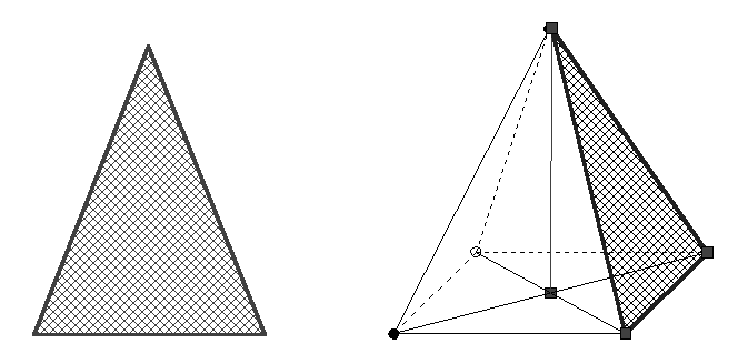
Figure 2.13
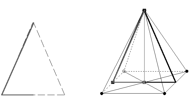
Figure 2.14
the angle between side height and base (Figure 2.14);the angle between lateral edge and a base diagonal (Figure 2.15):
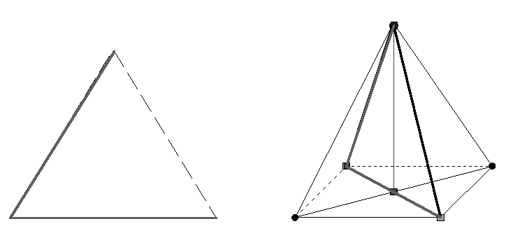
Figure 2.15
We put a pentagonal section in the pyramid defined by three edge points and see the one axis symmetrical section represented in true form (Figure 2.16.1).
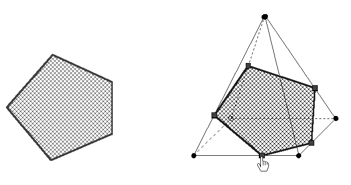
Figure 2.16.1 On request the solid rotates so automatically that this area assumes its true form inside this solid(Figure 2.16.2; one also can try this by manual contolled rotation, at this the angle of deviation is shown.
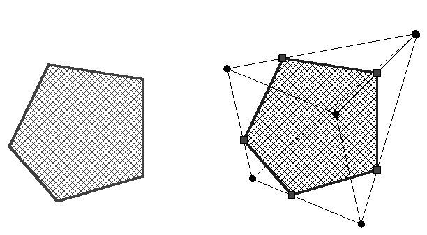
Figure 2.16.2
We vary the form of this pentagonal area by parallel moving (Figure 2.16.3, a kite – for example).
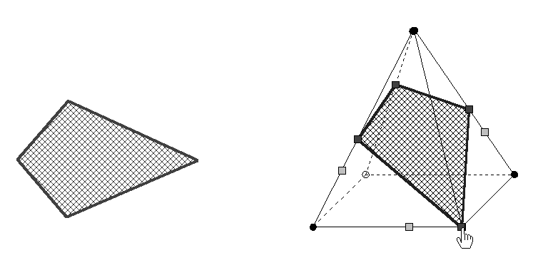
Figure 2.16.3
How does look like the sides of the polygonal section in a net of the corresponding solids and how do they change? The illustrations show this for the parallel moving at examples in figures 2.17.1 and 2.17.2.
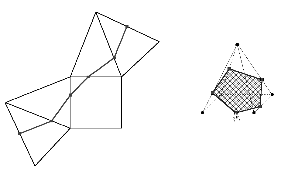
Figure 2.17.1

Figure 2.17.2
The variation of the polygonal forms can be visualized also by three table projection (Figure 2.18).
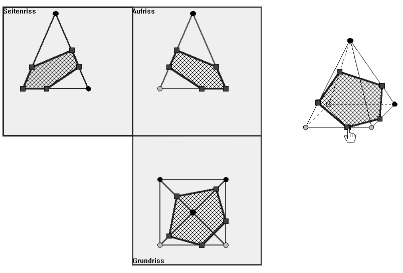
Figure 2.18
The initial pentagon can be rotated also around one of its sides (Figure 2.19) etc.
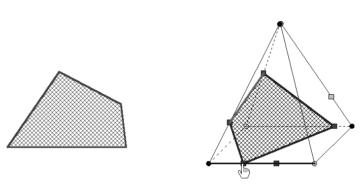
Figure 2.19
2.2.4 Particular lines in and on the pyramid
We confine ourselves to three examples of kinds of line in the square pyramid respectively. we start the investigation on segments connecting each base vertex with the midpoint of the opposite lateral edge (Figure 2.20.1). 
Figure 2.20.1
These lines intersect each other in one point. This quality also remains unchanged, if we drag the top of the pyramid (Figure 2.20.2);
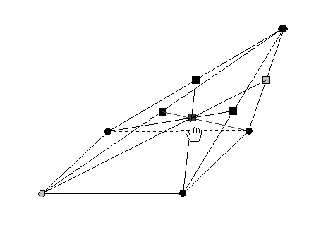
Figure 2.20.2
in addition, we can check with the option "partial point" (tool bar " Generation of solid points and line segments ") What’s the ratio for the point of intersection. This ratio is invariant; its value: 2:1, measured from base vertex. If we drop the perpendicular lines from the midpoints of the base edges on the opposite triangular faces, then these lines intersect as long as the base centre of the pyramid does coincide with the foot point of the height (Figure 2.21.1).
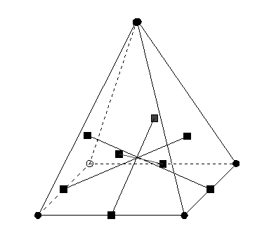
Figure 2.21.1 If this isn't the case any more, then the four lines have altogether no one common point (Figure 2.21.2).
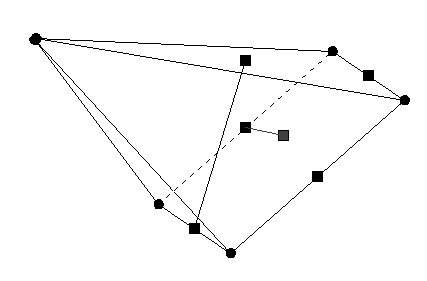
Figure 2.21.2
If we draw the points of gravitude of the triangular faces and connect them to a quadrangle then this quadrangle has the proporty of a square even if we drag the top of the pyramid (Figure 2.22.1-2.22.3)
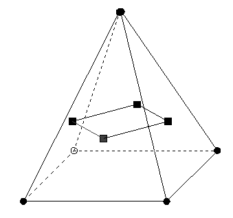
Figure 2.22.1
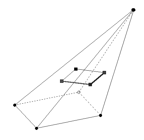
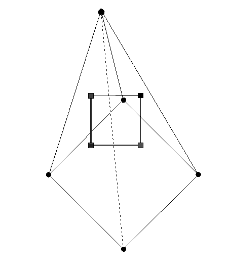
Figure 2.22.2 Figure 2.22.3
We most simply can check this experimentally by the fact that e.g. we measure the angle between adjacent sides and the lengths of the sides. If we drag the square base even to any convex quadrangle the shape of the square from the points of gratitude is invariant; what could be checked again experimentally? (Figure 2.22.4)
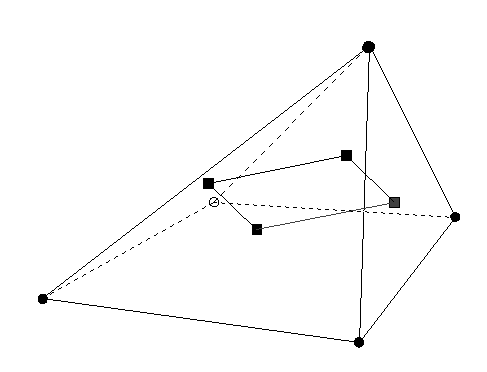
Figure 2.22.4
We close this section with an example of the shortest line (geodesic line) on the surface of a solid.
You can produce between two points on the pyramid surface (e.g. one lies on a lateral edge, the different one in the base, Figure 2.23.1) many connections consisting of line segments.
Figure 2.23.1
As example we draw a connection consisting of three line segments (Figure 2.23.2),
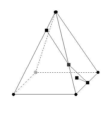
Figure 2.23.2
Which one among these unions of line segnments is of minimal length?
KOERPERGEOMETRIE has a corresponding option for the construction of a shortest way which we invoke (Figure 2.23.3).
Figure 2.23.3
We check the minimal length by the fact that the union of the connecing line segments is forming a line segment (Figure 2.23.4).
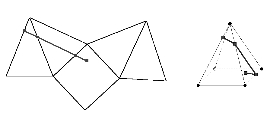
Figure 2.23.4
2.2.5 Halve pyramids
We select the section tool, wich is sectioning a solid into two parts length ways by a plane defined by three selected points. With this option and the automatic volume measuring (surface measuring) we solve experimentally the open task: Find all typical volume bisections of the square pyramid? (Of course every volume bisection of a convex solid is a surface bisection at the same time, what as a byproduct at the processing of the task.)
The axis section through the midpoint of a base edge shows figure 2.24.1.
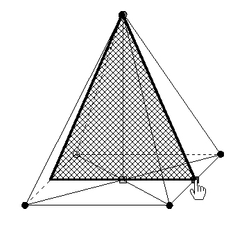
Figure 2.24.1
Result of the executed section: Figure 2.24.2.
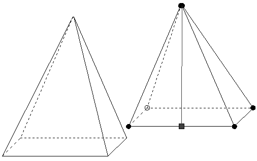
Figure 2.24.2
By a vertex of the base a further axis section is defined (Figure 2.25.1; Ergebnis: Figure 2.25.2).
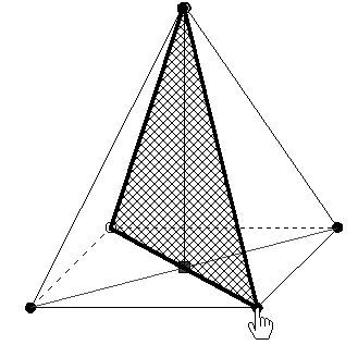
Figure 2.25.1
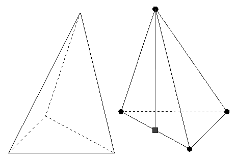
Figure 2.25.2
In the following we only give the section: Any other axis section determined by an arbitrary point on a bottom edge generates a pyramid bisection (Figure 2.26).
Figure 2.26
A section which contains the bottom edge and a point of an opposite lateral edge is halving also (Figure 2.27).
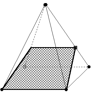
Figure 2.27
Three special point with the exception of vertices form also a halving section on different lateral edges.The following cases do arise: No section line is parallel to a bottom edge (Figure 2.28);
Figure 2.28
at least a section line is parallel to a bottom edge: With a section line a second is also parallel to a bottom edge (Figure 2.29),
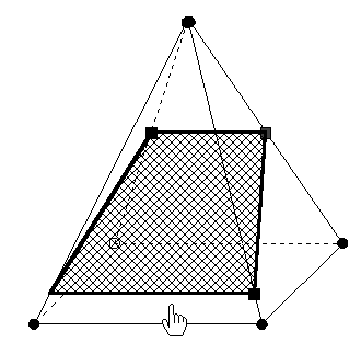
Figure 2.29
or it is parallelly to the base and there is a section which bisects the square pyramid into a small square pyramid and a pyramid frustum (Figure 2.30).
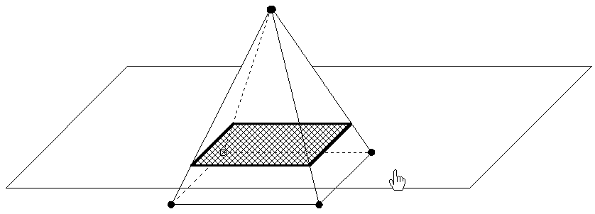
Figure 2.30
We create the frustum with the second section tool: A plane which can be parallelly dragged as cutting plane is defined alternatively. A horizontal plane is chosen in figure 2.30. Like in the preciding cases, the nets of both the solid halves can be generated (Figure 2.31.1/2).
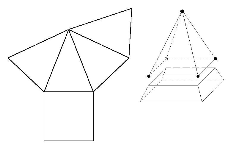
Figure 2.31.1

Figure 2.31.2
2.2.6 The truncated pyramid
The Babylonian derivation of the volume formula for the pyramid frustum (Figure 2.32.1) created like in figure 2.30 presupposes its reduction in parts of which the volume formulae are known already . We use the second section tool to execute the suitable sections with movable vertical sections (Figure 2.32.2).
Figure 2.32.1
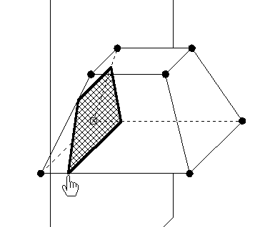
Figure 2.32.2
Figure 2.32.3
The figure 2.32.3 shows us the pyramid frustum with the corresponding section lines, on which we look at different positions by solid rotations (Figure 2.32.4/5).
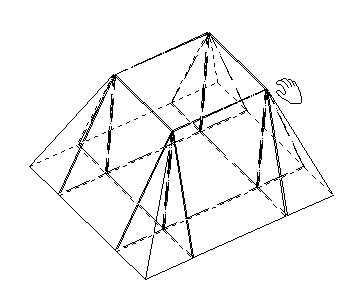
Figure 2.32.4
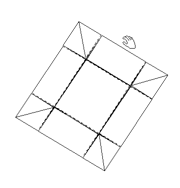
Figure 2.32.5
We drag the parts from each other (Figure 2.32.6),
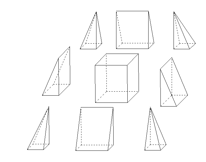
Figure 2.32.6
and join them together to a square pyramid and to two trihedral prisms; a square cuboid is left (Figure 2.32.7).

Figure 2.32.7
With little fiddly rotations around axes to be chosen suitably we get a cuboid from the two prisms (Figure 2.32.8).
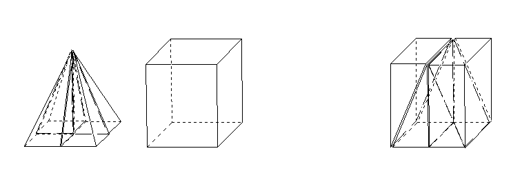
Figure 2.32.8
Now we can use the known volume formulae with the corresponding notions to derive the formula for the frustum.
- Cutting off pyramids
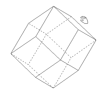 Figure 2.33.1
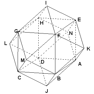
The figure 2.33.1 shows a dodecahedron consisting of mutually congruent rhombs .Therefore one also calls this solid rhomb dodecahedron. Its vertices are formed from three or four rhombs; therefor it isn't a regular solid.
It can be measured with the measuring tools of KOERPERGEOMETRIE. A cube can be inscribed into this solid (Figure 2.33.2).
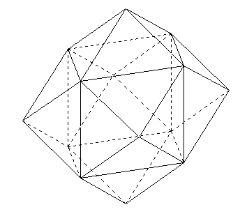
Figure 2.33.2
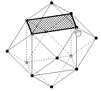 The rhomb dodecahedron can be combined from four square pyramids and a cube cube. We cut off one of these pyramids (Figure 2.33.3) and define its base as plan for reflection (Figure 2.33.4) and reflect the pyramid.
Figure 2.33.3
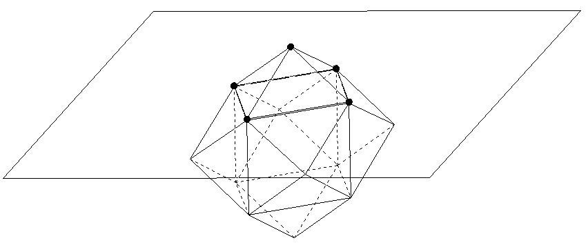
Figure 2.33.4
The top of the mirrored pyramid coincides with the centre of the cube (Figure 2.33.5);
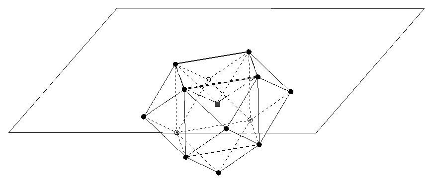
Figure 2.33.5
the pyramid height is halfly as long as the cube edge.
About the implementation of solids by coordinates: Therefore the input of the rhomb dodecahedron starts from the vertices of a unit cube, upon which we put twelve suitable rhombs . One can create the following programs for the two solids with any text editor.
|
Program for the rhomb dodecahedron with inscribed cube:
1,E, 1.0,-1.0, 0.0,A
1,E, 1.0, 0.0, 0.0,B
1,E, 0.0, 0.0, 0.0,C
1,E, 0.0,-1.0, 0.0,D
1,E, 1.0,-1.0, 1.0,E
1,E, 1.0, 0.0, 1.0,F
1,E, 0.0, 0.0, 1.0,G
1,E, 0.0,-1.0, 1.0,H
1,E, 0.5,-0.5, 1.5,I
1,E, 0.5,-0.5,-0.5,J
1,E, 1.5,-0.5, 0.5,K
1,E,-0.5,-0.5, 0.5,L
1,E, 0.5, 0.5, 0.5,M
1,E, 0.5,-1.5, 0.5,N
1,F,EFI
1,F,FGI
1,F,GHI
1,F,HEI
1,F,BAJ
1,F,CBJ
1,F,DCJ
1,F,ADJ
1,F,ABK
1,F,BFK
1,F,FEK
1,F,EAK
1,F,CDL
1,F,DHL
1,F,HGL
1,F,GCL
1,F,BCM
1,F,CGM
1,F,GFM
1,F,FBM
1,F,DAN
1,F,AEN
1,F,EHN
1,F,HDN |
Program for the rhomb dodecahedron:
1,E, 1.0,-1.0, 0.0,A
1,E, 1.0, 0.0, 0.0,B
1,E, 0.0, 0.0, 0.0,C
1,E, 0.0,-1.0, 0.0,D
1,E, 1.0,-1.0, 1.0,E
1,E, 1.0, 0.0, 1.0,F
1,E, 0.0, 0.0, 1.0,G
1,E, 0.0,-1.0, 1.0,H
1,E, 0.5,-0.5, 1.5,I
1,E, 0.5,-0.5,-0.5,J
1,E, 1.5,-0.5, 0.5,K
1,E,-0.5,-0.5, 0.5,L
1,E, 0.5, 0.5, 0.5,M
1,E, 0.5,-1.5, 0.5,N
1,F,KFIE
1,F,MGIF
1,F,LHIG
1,F,NEIH
1,F,KBMF
1,F,MCLG
1,F,LDNH
1,F,NAKE
1,F,KAJB
1,F,MBJC
1,F,LCJD
1,F,NDJA |
|
Remarks: 1stand for the solid to be defined (here only for a subsolid), E (F) for the vertices to be defined, (faces); A, B, C, D, F, G, H are the denotions for the vertices of the cubeI, I,J,K,L,M,N for the tops of the pyramids.
C forms the coordinate origin; the inscribed cube is assumed as unit cube. |
|
Therefore the volume of the rhomb dodecahedron is twice as large as that one of the cube.We also can see this by the fact that we form a cube which is congruent to the inscribed out of the six pyramids put on.To this we cut off one by one the four pyramids and turn these suitably around one of her bottom edges (Figure 2.34.1/2) and move the fifth into the gap left (Figure 2.34.3).
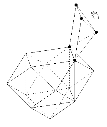
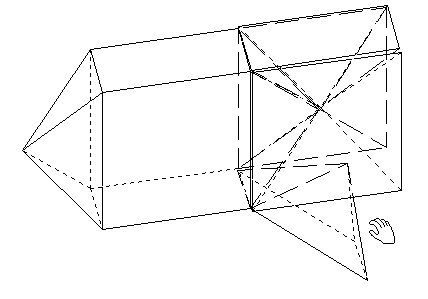
Figure 2.34.1/2
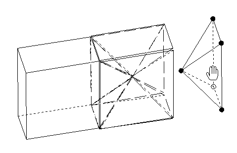 Figure 2.34.3
A further example of cutting off pyramids:
We define a four-sided double pyramid with equal edges (regular octahedron), cut off its six corners up to the midpoints of the edges and get a solid with six squares and eight equilateral triangles as faces (cubo octahedron).
2.2.8 Cut pyramids out
Square pyramids can be cut out of solids. A square cuboid is among others suitable for this: First we draw the pyramid into the square cuboid, so to speak as project for the cutting procedure (Figure 2.35.1), we then cut like in figure 2.35.2 and 2.35.3 using the first cutting tool.
Figure 2.35.1
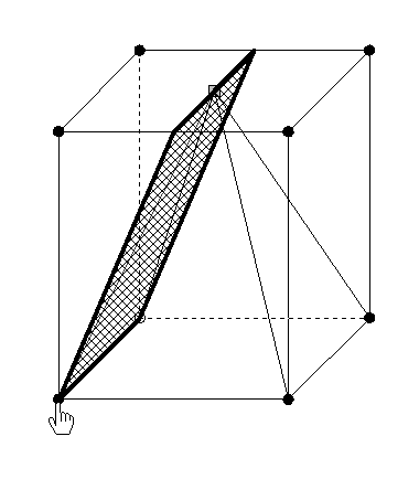
Figure 2.35.1
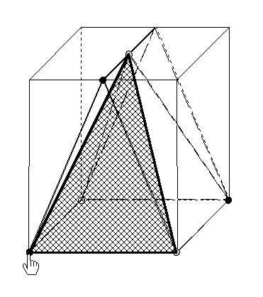
Figure 2.35.3
We get four "scrap solids" (Figure 2.35.4).
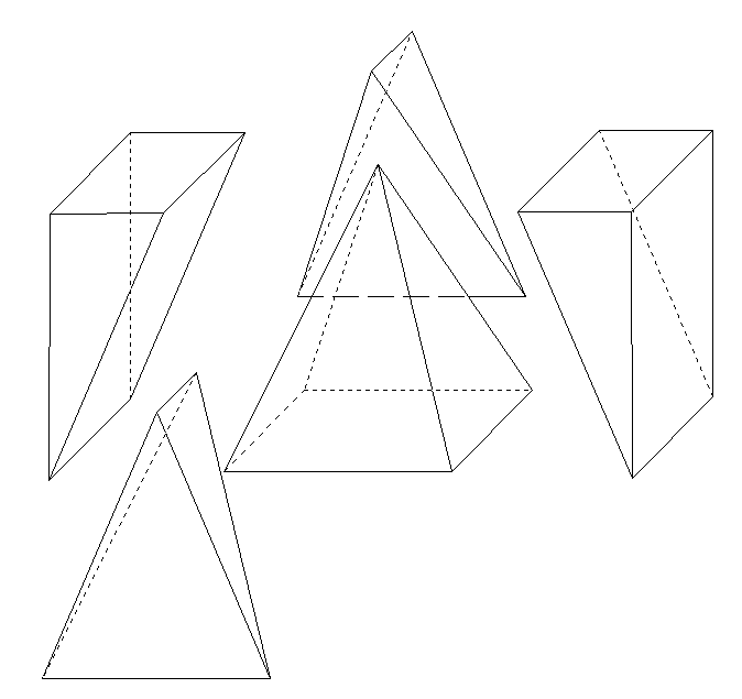
Figure 2.35.4
If we use the second section tool, then we get a different solution (Figure 2.36.1/2);
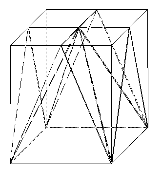
Figure 2.36.1
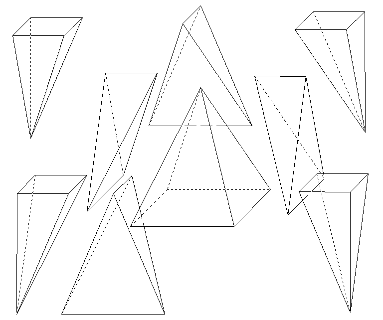
Figure 2.36.2
If we partially drag off the generated subsolids then we get an interference of two roofs (Figure 2.36.3).
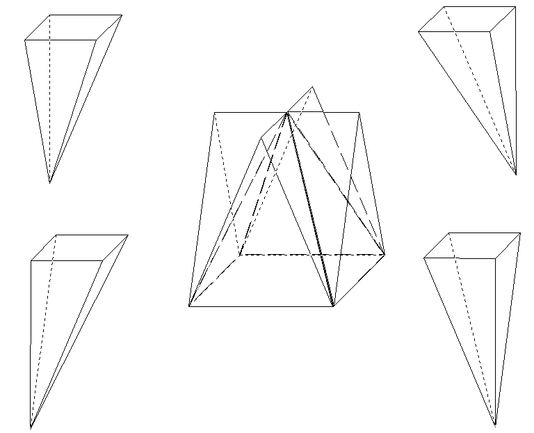
Figure 2.36.3
We also can the cube dissect into pyramids. We execute only one of the possibilities here. As result we get three mutually congruent pyramids with square bases; unfortunately one of the pyramids is always dissected into two trihedral pyramids (Figure 2.37.1/2).
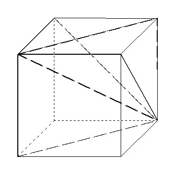
Figure 2.37.1
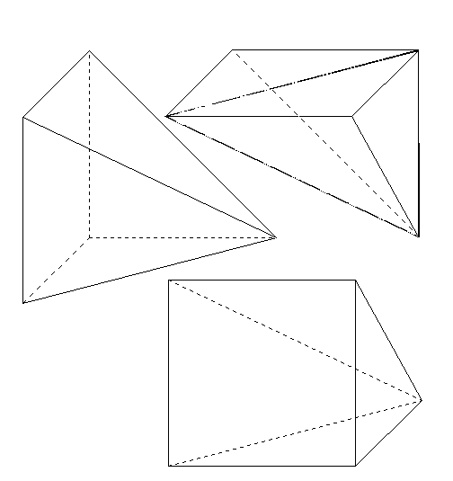
Figure 2.37.2
The net of such a pyramid shows the true form of the faces to be described (Figure 2.37.3).
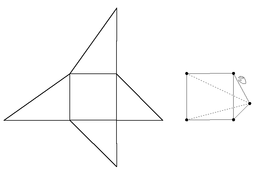
Figure 2.37.3
2.2.9 Pyramid dissections into various solids
A double pyramid shall be cut out of a square pyramid.
The 2.38.1 figure shows the project for this.
Figure 2.38.1
With the first section tool we get a dissection like in figure 2.38.2.
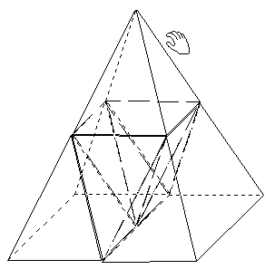
Figure 2.38.2
We have a look at this dissection by rotating the solid (Figure 2.38.3).
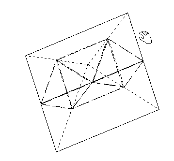
Figure 2.38.3
The result of the dragging apart shows the "exploded view" in figure 2.38.4.
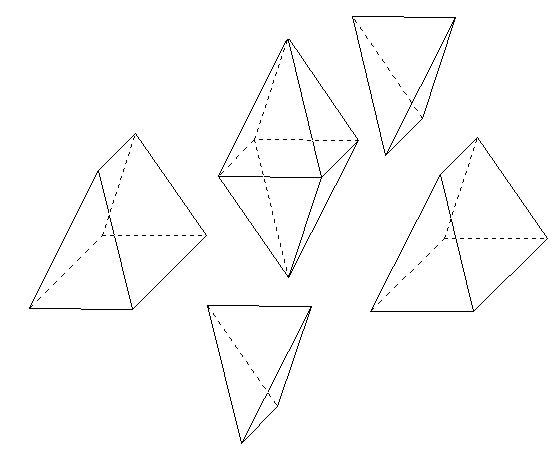
Figure 2.38.4
The whole section scene can be rotated around. The parts form a "pyramid jigsaw puzzle". The net of the octahedron can be seen in figure 38.5; the jigsaw puzzle parts are also made haptically available by printout .
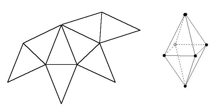
Figure 2.38.5
Production of an "irregular" jigsaw puzzle: For example we put two horizontal and two vertical sections in a square pyramid (Figure 2.39.1)
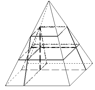
Figure 2.39.1
We drag the parts from each other and mix them (Figure 2.39.2).
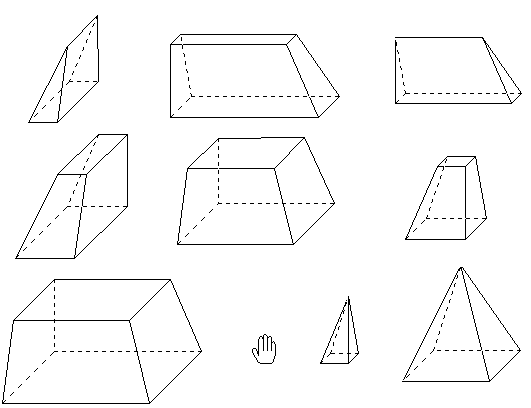
Figure 2.39.2
It is a challenging task to fit up these mixed parts to a square pyramid.
2.2.10 Fitting up pyramids with various solids
We can combine a pyramid with itself and different basic solids; three of such results of combination show Figure 2.40.1 – 2.40.3.
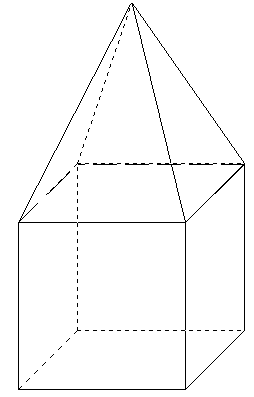
Figure 2.40.1 (Pyramid with pyramid) Figure 2.40.2 (Pyramid with cube)
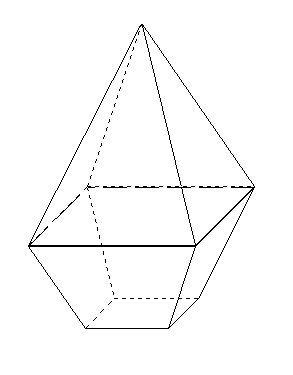
Figure 2.40.3 (Pyramid with pyramid frustum).
2.2.11 Inscribing and circumscribing pyramids
We select the "Inscribing" of square pyramid into the cube and we illustrate the result in a spatial corner and in the three plane projection (Figure 2.41.1/2); after a rotation it does look like in figure 2.41.3.
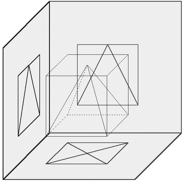
Figure 2.41.1
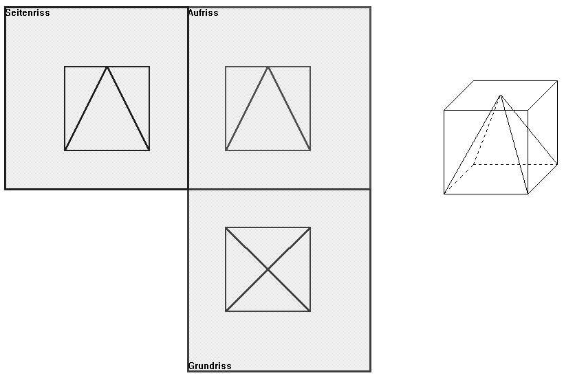
Figure 41.2
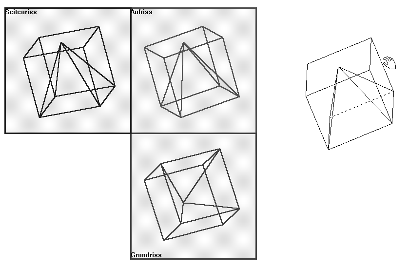
Figure 2.41.3
We inscribe the cube into a square pyramid or circumscribe a pyramid to the cube (Figure 2.42.1/2).
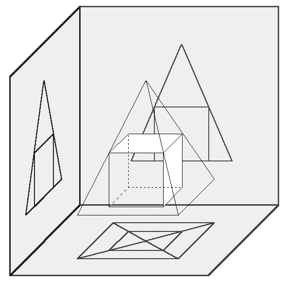
Figure 2.42.1
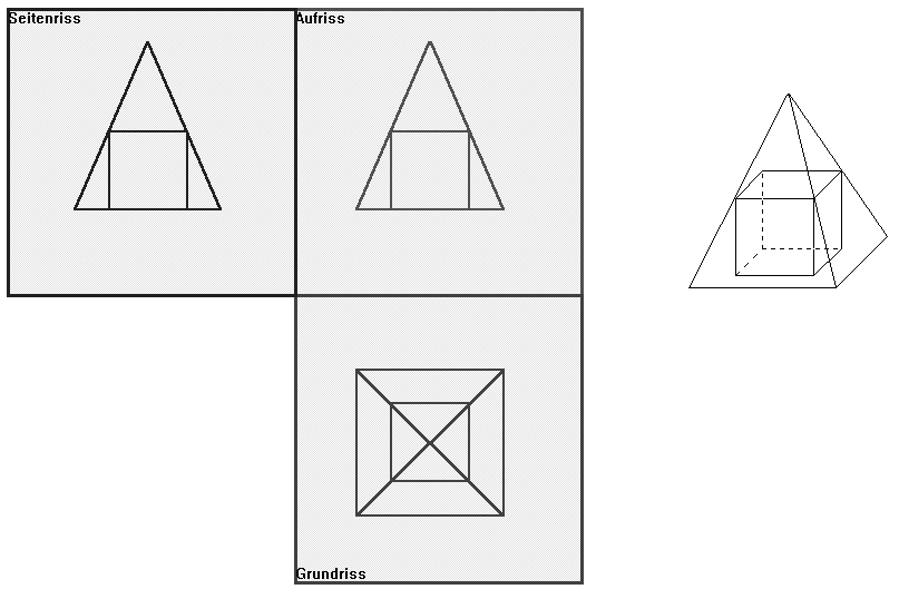
Figure 2.42.2
We also can inscribe a cylinder or the sphere into a square pyramid (Figure 2.43/44).
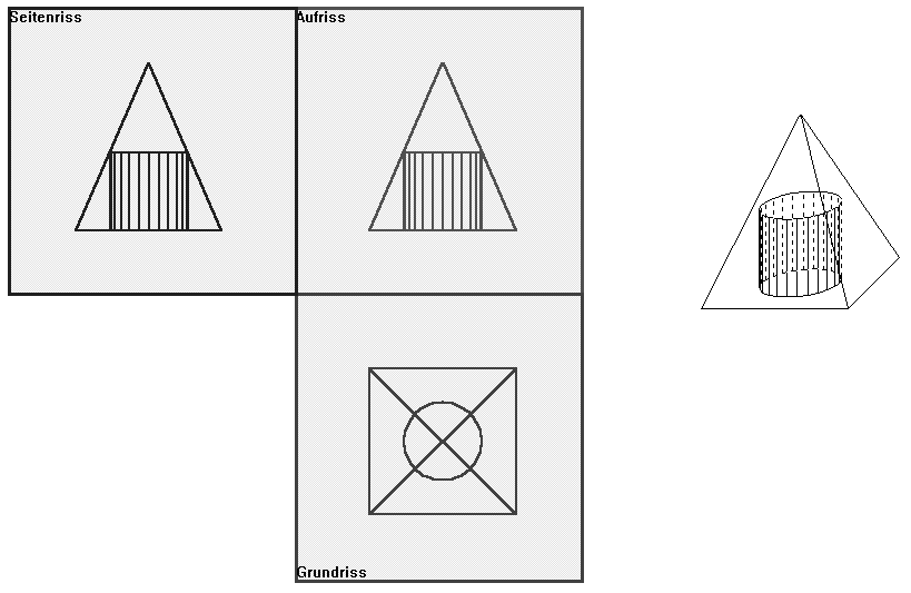
Figure 2.43

Figure 2.44
2.2.12 From the pyramid to the "cone"
The figures 45.1- 45.4 illustrate the approximative transition of the 4-sided pyramid -- to the "cone" of equal height and equal radius of the bottom area; at this the corresponding nets are also displayed, showing the regular base and the lateral surface of the pyramid for comparison purposes respectively.
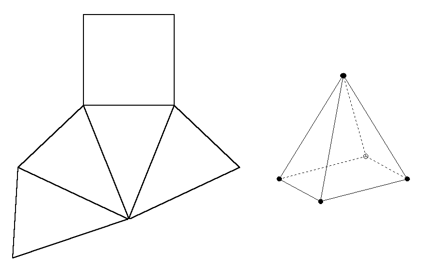
Figure 2.45.1
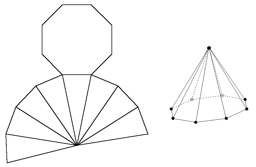
Figure 2.45.2

Figure 2.45.3
The solid in figure 2.45.4 is created with the cone button; however, we recognize by counting edges or vertices that it is actually.a 24-sided pyramid. In KOERPERGEOMETRIE a cone is always approximated by such a pyramid. –By dragging the top of cone to a skew one we get an aestheticaly looking net (Figure 2.46).
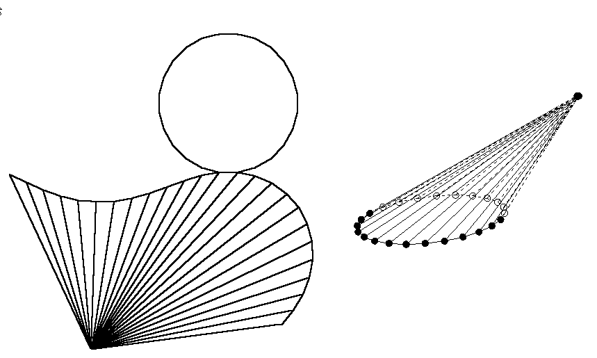
Figure 2.46
The cone can be created also as rotation solid. To this the triangular rotation profile must correspondingly be adjusted by dragging (Figure 2.47.1).
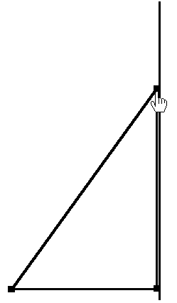
Figure 2.47.1
Depending on selected number n of facets one gets a n-sided pyramid (Figure 2.47.2, n = 4: square pyramid);
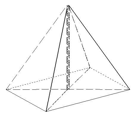
Figure 2.47.2
for the maximum number to facets we approximatively get a cone (Figure 2.47.3).
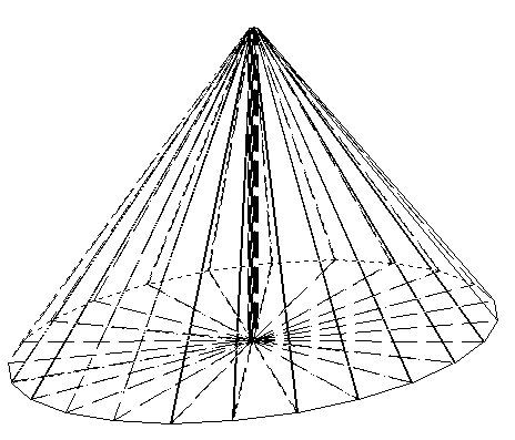
Figure 2.47.3
By dragging the rotation profile the arising of the rotation solid can be demonstrated (Figure 2.47.4).
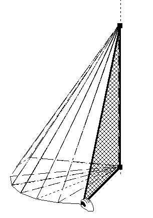
Figure 2.47.4
2.2.13 Different kinds of conical section
A plane parallel to the base cuts the cone into a circle (Figure 2.48.1).
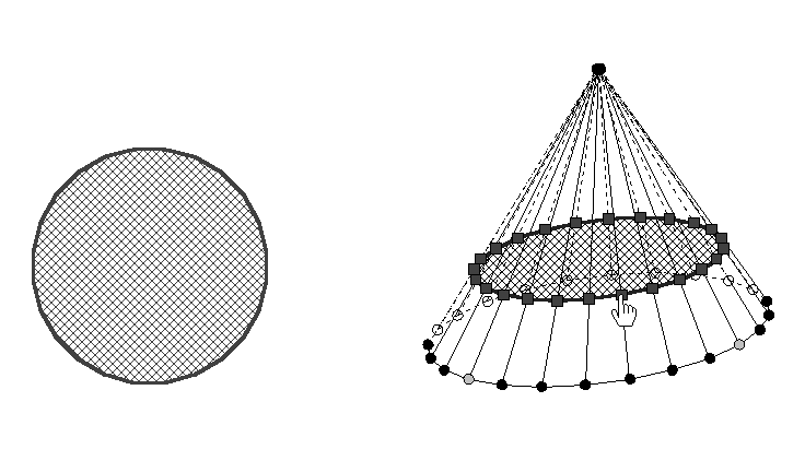
Figure 2.48.1
The type of conical section depends on the the size of the angle compared with the angle between the cone generating line and the base of the cone: we get an ellipse,
if this size is smaller (Figure 2.48.2); a hyperbola (Figure 2.48.3), if this size is greater and a parabola, if this size is equal.
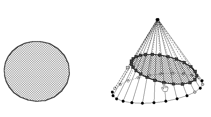
Figure 2.48.2
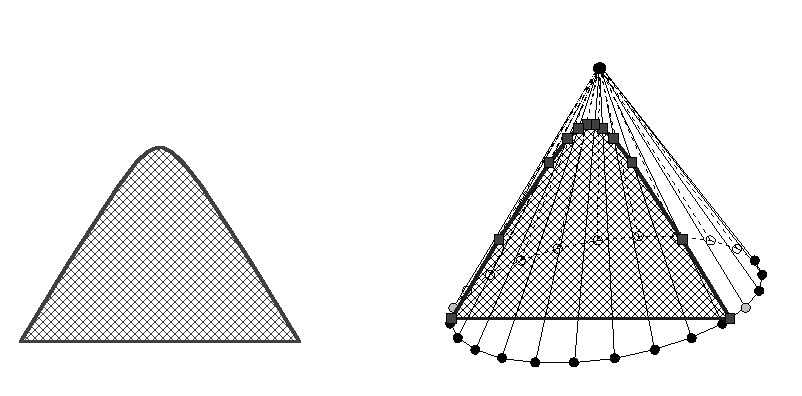
Figure 2.48.3
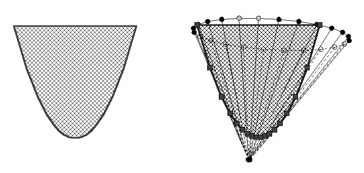
Figure 2.48.4
With the corresponding tools the angles in question can be measured.
We execute all the cuts of the mentioned sections now and represent the nets of the section solids in question: Cone frustum with circular base (Figure 2.49.1),
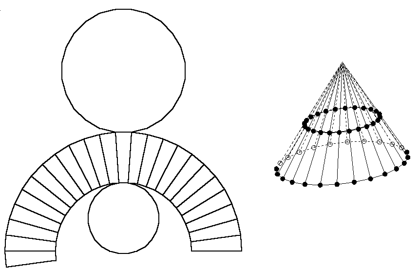
Figure 2.49.1
Cone frustum with an elliptic cover (Figure 2.49.2a)
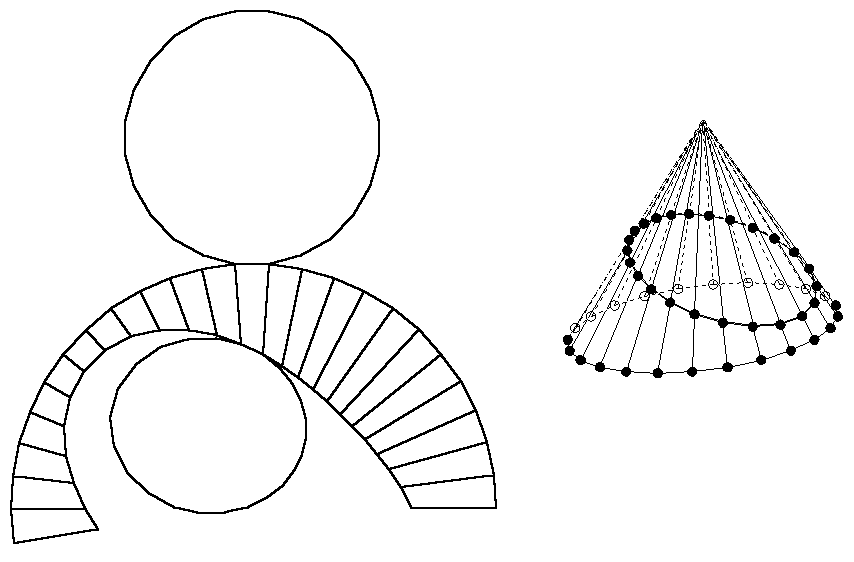
Figure 2.49.2a
and cone with elliptic base (Figure 2.49.2b),
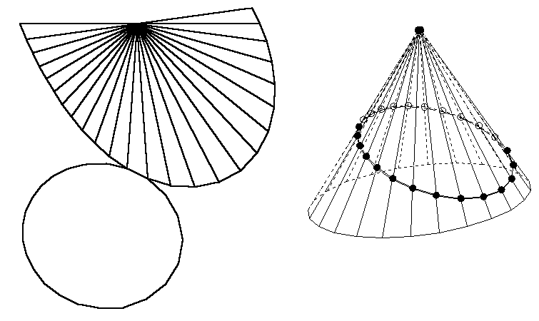
Figure 2.49.2b
Subsolids of the cone with sections of hyperbolic shape (Figure 2.49.3a/b).
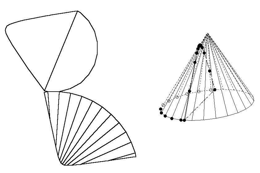
Figure 2.49.3a
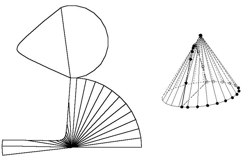
Figure 2.49.3b
Subsolids of the cone with sections of parabolic shape (Figure 2.49.4a/b).
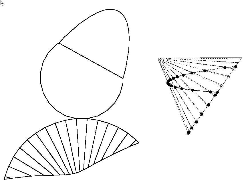
Figure 2.49.4a
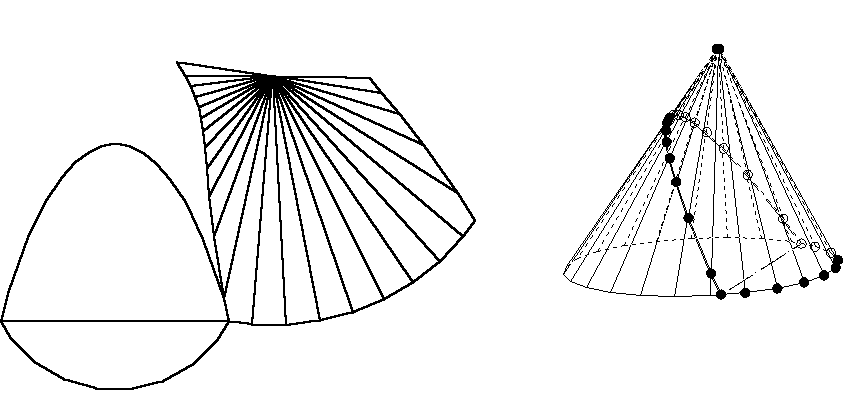
Figure 2.49.4b
The section outline can be anticipated befor the execution, for example for the elliptic section (Figure 2.50).
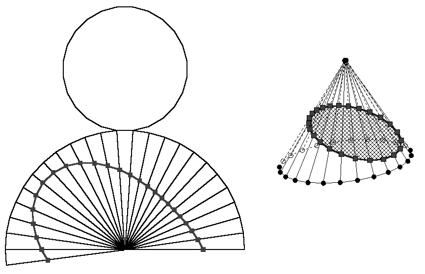
Figure 2.50
2.2.14 From cone to cylinder
The cylinder can be understood as a cone of which the top is dragged to "infinity" (Figure 2.51.1/2).

Figure 2.51.1 Figure 2.51.2
A net of the upright circular cylinder (Figure 2.52.1) is transformed to a net of an oblique circular cylinder with dynamic appearance (Figure 2.52.2).
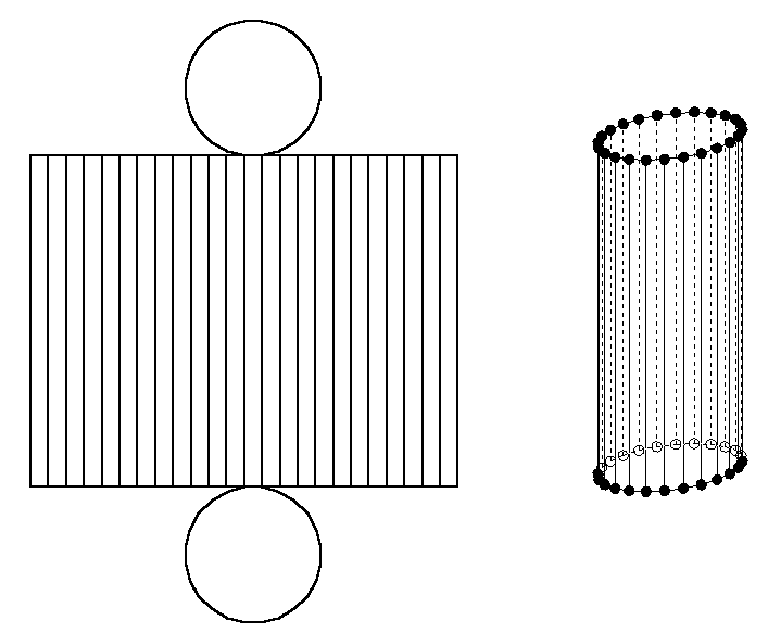
Figure 2.52.1
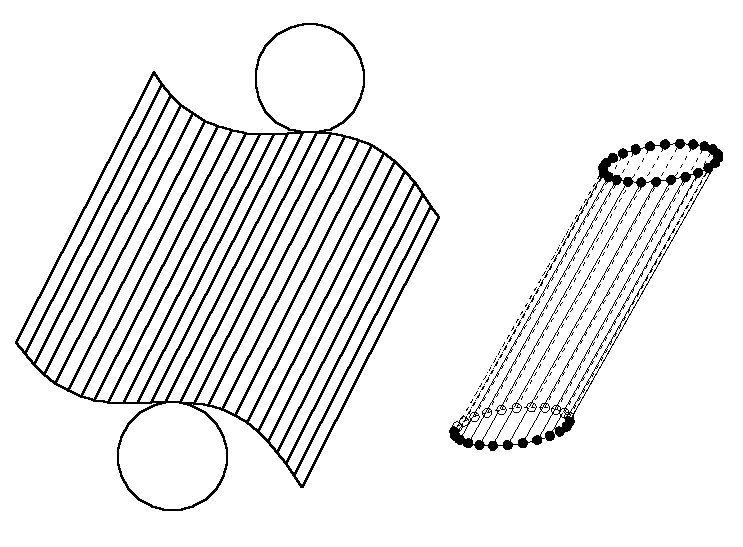
Figure 2.52.2
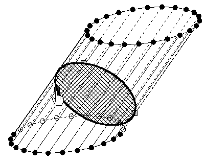
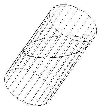
Figure 2.53.1/2
We make an oblique cylinder from an upright one, by executing a section vertically to a generating line and by suitably changing the position of one of the subsolids (Figure 2.53.1/2). The elliptic section produces a corresponding net like the skin of a sausage cut off (Figure 2.54.1/2).
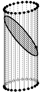
Figure 2.54.1
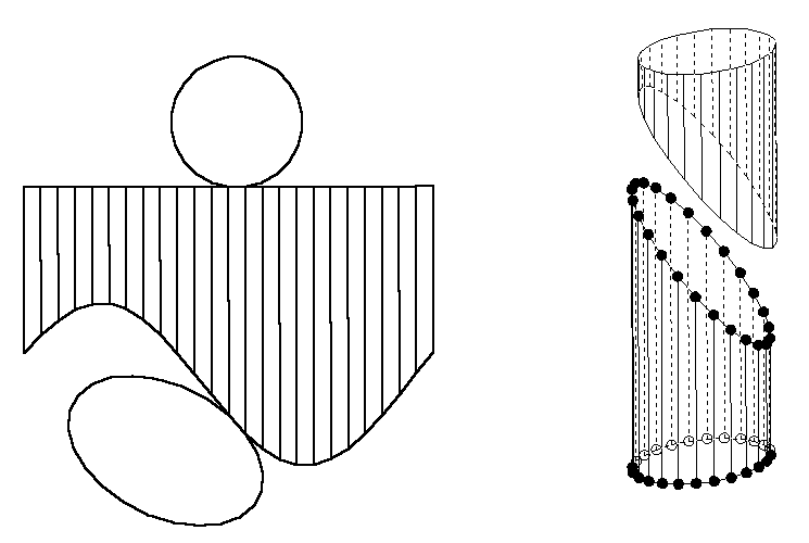
Figure 2.54.2
A creeper is climbing economically around a cylindrical tribe, namely on shortest way (Figure 2.55); this shows the line segment as shortest connecting line in the net...
Figure 2.55 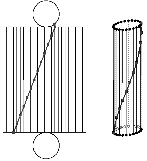
We close our excursion in KOERPERGEOMETRIE with the construction of a section solid (so-called multi-purpose stopper), which must fit to each of the three holes of the stencil given in figure 2.56.
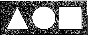
Figure 2.56
We adapt a cylinder in that way that its height is equal in size like its diameter (Figure 2.57.1).
In order to adapt this solid to the profile of equilateral triangle
we put two corresponding sections into the cylinder (Figure 2.57.2).
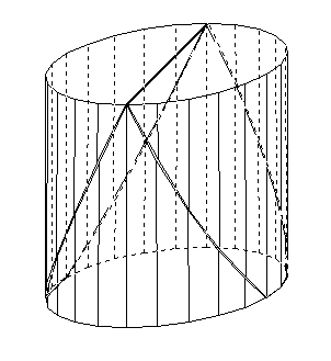
Figure 2.57.1/2
The figure 2.57.3 shows the separation of the sectional solids.
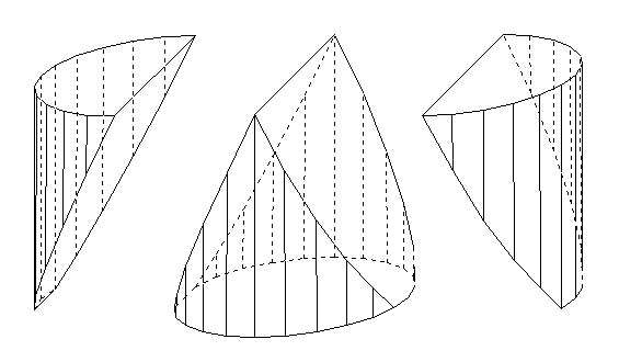
Figure 2.57.3
We make the multi-purpose stopper haptically accessibly to us with the generation of a net (Figure 2.57.4).
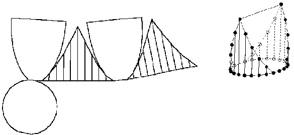
Figure 2.57.4
We can recognize in the three table projection that the constructed solid has the desired qualities (Figure 2.57.5).
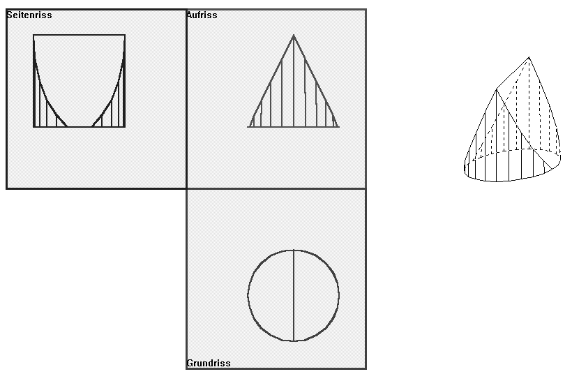
Figure 2.57.5
- COMPUTER SUPPORTED TREATMENT
OF (SPATIAL) GEOMETRIC CALCULATION
We explain new standards for solving of geometrical calculation tasks in dependence of computer tools chosen suitably. We can distinguish the following kinds of computer supported solution standard in the essential :
- the computer graphical solving
- the computer numeric and algebraic solving.
The computer graphical solution depends on the figural representation of the solid to
be calculated.in a graphical tool like KOERPERGEOMETRIE with its possibilities of varying by dragging, constructing and measuring. Of course solving graphically is only possible for special calculation tasks, i.e. tasks without treatment of calculation variables. The advantage of solving consists in the experimental, clear geometric understanding of the task without hindrance by the arithmetical and algebraic barriers.
The the computer numeric and algebraic solving means the solution of special and general geometric tasks with support of the computer numeric and algebraic components for mathematical assistance programmes, here for these of DERIVE and MATHEMATICA.
There are two kinds of these solving methods to be distinguished:
- the "simulation method" by means of DERIVE
- the "formulation method" (Ansatz-method) by means of MATHEMATICA.
The simulation method: The simulation method is simulating the process of manual solution using all the support of automatically algebraic execution by the corresponding options. -
It is to build an "essential" equation (formula etc.) in which all variables with the exception of the sought-after ones are to be substituted. To win the variables to be replaced, one needs auxiliary equations, which are to be resolved automatically etc..The substitutions carried out interactively by means of the option "Substitute" or by means of definition of global variables and by "Simplify" into the depth. The essential equation is then resolved for the variable sought-after. The general calculation task is solved with that. Into the algebraic term of solution the given numeric data are to be inserted for the solution of a special calculation task in order to get an approximative or an exact numeric solution. One takes the conditions for solvebility from the algebraic solution term. For further calculation and modular work one defines algebraically calculation macros in dependance of the givens using suitable denotions.
The formulation method:
A formulation consists of three sets:
-
A set of linear and/or non-linear equations with target variables as well as auxiliary
variables which together form a system of implicit or explicit algebraic equations.
-
The subset of target variables for which the system of equations is to be solved.
-
The subset of auxiliary variables which are to be eliminated.
For special calculation tasks the concrete value assignments still have to be
added.
To find such a formulation, a knowledge of facts and procedures related to the problem is required, in particular appropriate heuristic knowledge. Some general instructions for the solving of a mathematical problem were given by G. Polya, 'father of mathematical heuristics in schools', in his well known book How to Solve It? (Princton, 1944). They also contain the development of a solution plan in the narrow sense, the development of the above formulation.
HOW DOES ONE LOOK FOR THE SOLUTION?
FIRST -
You must understand the problem
SECOND -
Look for the connection between the data and the unknown
You might have to look at auxiliary problems if an immediate connection cannot be found
Finally, you must formulate a solution plan
THIRD -
Carry out your plan
FOURTH -
Check the solution you obtain
Only the third step is essentially altered when an Auto-Solver is used: rather than 'Carry out your plan', it becomes 'Use an Auto-Solver to carry out your plan'.
Illustration of the above scarcely described methods by the following example:
Statement of the problem:
Given: A square-based right pyramid has a volume 50 cm3 and a surface area 100 cm2.
To find: Determine the base length and height of the pyramid.
Graphical solution:
We select from the basic solid repertoire a right square-based pyramid with variable base length a and variable height. We use the online-measurement and drag the pyramid until approximate values for V (= 50 cm3) and S (= 100 cm2) are achieved and then read off the corresponding base length (a) and height (h), obtaining a = 6.2 cm, h = 3.9 cm (Figure 3.1).

Figure 3.1
Solution by the Formulation-method:
Numeric solution:
Fiugure 3.2
We can either make a sketch or use one of the figures already constructed for the graphical solution (Figure ). Starting from the given data we develop a formulation for the solution in as systematic a manner as possible; in this case a top-down formulation (Input 1). The given variables are V, S; the target variables are a, h; the auxiliary variables are B, LS, T and hT. A set of eight equations is formulated in these eight variables. These are:
V = 50 Volume of pyramid (given)
S = 100 Surface area of pyramid (given)
V = B h / 3 Volume of pyramid as (1/3) x base x height
S = B + LS Surface area of pyramid as area of base + area of four triangu-
lar sides
B = a2 Base area for square pyramid of side length a
LS = 4T Surface area of the four triangular sides (Lateral Surface)
T = (a/2) hT Surface area of one triangular side
hT2 = (a/2)2 + h2 Height of a triangular side (using Pythagoras‘ theorem)
There are four solutions of which only two correspond to positive solutions of a and h. We illustrate a variant auto-solver – NSolvePositive – which does not produce the two extraneous negative roots which would otherwise appear (Input and Output 1).
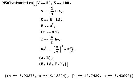
Input and Output 1
One of the two solutions is already known, having been found by graphical means (Figure 3.1). The other solution was overlooked while constructing the graphical solution. As well as the flat but broad pyramid there is a higher narrower one, both of which match the given data for surface and volume.
Algebraic solution:
To get a grasp of the class of all problems represented by the particular solution we need to determine the exact general solution for given S and V. From this we can obtain the conditions for solvability, that is, relations between S and V for which meaningful solutions exist; according to the requirements of the problem these must be real positive solutions.
We only need to remove the ‘N’ from NSolveReal (or NPositiveReal) and remove the two assignments V = 50, S = 100 (Input 2). The exact resolution of the general formulation leads to four solutions (Output 2), of which only the second and the fourth are acceptable. (This raises the question of why there are four solutions. The explanation is that manual resolving the formulation for a leads to a quartic equation.)
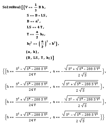
Input and Output 2
Note that in problems where we cannot easily recognise the acceptable solutions among the general ones, we only need to substitute an approximating command (e.g. NSolveReal for SolveReal) to the exact solutions and supply given data.
Condition for real solutions:
S4 – 288 x S x V2 ³
0, or S3 ³
2 x (12 x V) 2
Conditions for positive real solutions:
S2 – (S4 – 288 x S x V2) 1/2 > 0 and 288 x S x V2 > 0
which are satisfied for S > 0 and V > 0.
Solution by the simulation method:
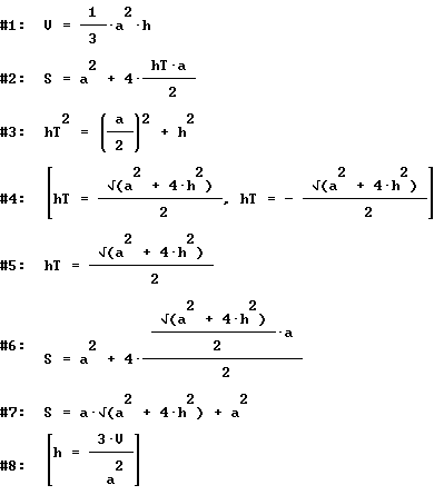
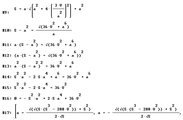
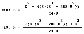
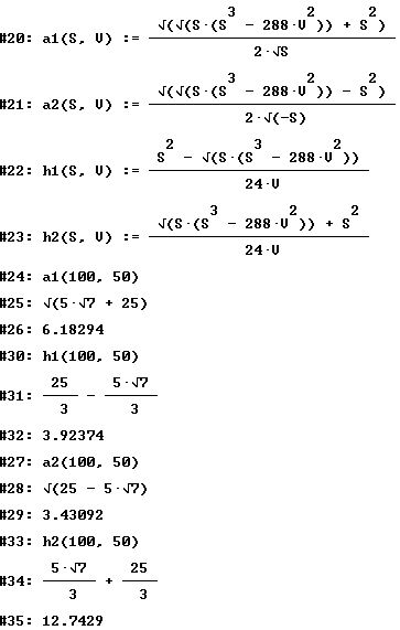
We only display the printout of the process of solution using DERIVE. The lines 20-23 show the defined calculation macros; the special calculation task is solved at the end.

Final remark:
All methods complete each other, since various, but essential aspects of solving calculation problems are taken into account.
The solution standards aren't to be seen isolated but they induce a computer supported complete treatment of calculation tasks.
2.4 Some final comments
Comment 1: Of course KOERPERGEOMETRIE isn't suitable for the solution of all (open) spatial geometrical tasks. For example the discovery of all the convex polyhedra whose surface consists of equilateral triangles and squares has to be executed with suitable materials.
Comment 2:
The use of adequate computer tools to the production of spatial geometrical objects opens up new possibilities for the solution of open problems. At this the computer is an important medium
-
for the extension of knowledge fields which can be treated only hardly in the lesson with the conventional media
-
for the reinforcements of creative intellectual performances
-
for the flexible and economic reorganization of working processes and results.
Commet 3:
What’s the meaning of computer represented spatial geometry from point of view of the student for understanding our world, for private life and for the professional future. The spatial geometry lesson could for example make the connection to the numerous 3-D computer graphics applications, being increasingly trusted to the naive user in the form of aesthetic animations, 3-D games, versatile 3-D CAD tools (for example for living space planning) and virtual-reality applications. In connection with that, the research question still to be answered in the general rises: How "spatial ability and imagination" can be developed and excercised by the use of spatial geometry software? Because the development and training of the spatial ability and imagination is an original task of the spatial geometry lesson!
Comment 4: How computer supported learning of spatial geometry could look like in near future?
Learning of spatial geometry in virtual realities:The use of today's spatial geometry programs still has student and computer system left separated: The student can only indirectly communicate with the computer for example using the graphical device 'mouse'; therefore her/his kinästhetic feelings and experiences are very restricted; he/she lets execute options and watches the (spatial) result on the planar screen; the spatial interpretation can only be improved by stereographic representations and the use of red-green spectacles.The computer generation of so-called virtual realities partially cancels the limits between the systems student and computer:
By means of a suitable audio-visual interface, the eye phone and the tactile interfac data glove it is possible , that the student has the (illusionary) sensation to move and act with her/his whole body inside a simulated three dimensional world for example carrying out virtual operations at objects of the virtual reality.
The following scenario for a future geometry learning is conceivable: The geometry learner proceeds as Cybernaut in a three-dimensional geometrical world of the forms for example in one for investigating polyhedra. He goes for a walk between the solids, does look at them from the frog or the bird's-eye view, climbs on the solids around, feels the pointed corners and the sharp edges, he slips down the slippery solid faces, he penetrates into the solids and views them from inside; he/she moves the solids, combines them, develops them to the plane, changes its size, he deforms them arbitrarily and carries out operations at them, for example section operations or he/she 'plays' him/herself a solid and e.g. 'experiences' the rolling as a solid etc.
How will emboss such a computer represented spatial geometry the 'imagination' of geometry by the students? How will change their relation to the not virtual three-dimensional world surrounding?
3 Bibliography
3.1 Selected contributions of the author
Schumann, H.
Reflections on the use of the turtlegraphics of LOGO within the teaching
of geometry.
Konzeptionelle Ueberlegungen zum Einsatz der Grafikkomponente von LOGO im
Geometrieunterricht.
Log In. (Sep 1986) v. 6(4) p. 40-44.
Schumann, H.
Geometric constructions with an extended LOGO.
Geometrische Konstruktionen mit einer Erweiterung von LOGO.
Log In. (1988) v. 8(1) p. 53-57.
Schumann, H.
The computer as a tool for geometric constructions.
Der Computer als Werkzeug zum Konstruieren im Geometrieunterricht.
ZDM Zentralbl. Didakt. Math. (Dec 1988) v. 20(6) p. 248-263.
Schumann, H.
FORM – computer animation for planar geometry.
FORM.
Duisburg: CoMet Verlag fuer Unterrichtssoftware. 1989. 51 p. With 5 1/4''
diskette.
Schumann, H.
A first interactive 2-D-graphics-package. For geomtrical constructions at
school.
Ein erstes interaktives 2-D-Grafiksystem. Zum schulgeometrischen
Konstruieren.
Log In. (1989) v. 9(4) p. 30-33.
Schumann, H.
The computer as a tool for geometric constructions.
Der Computer als Hilfsmittel fuer die geometrische Konstruktion.
Micromath. (Aut 1989) v. 5(3) p. 53-56.
Schumann, H.
Intersection of straight lines and circles by computer.
Computergeeignete Schnittpunktbestimmung von Geraden und Kreisen.
Prax. Math. (15 Jan 1989) v. 31(1) p. 32-38.
Schumann, H.
Finding theorems by continuous variation of geometrical configurations
with the computer as interactive instrument.
Satzfindung durch kontinuierliches Variieren geometrischer
Konfigurationen mit dem Computer als interaktivem Werkzeug.
Mathematikunterricht. (Jul 1989) v. 35(4) p. 22-37.
Schumann, H.
A suitable graphics system for classroom constructions in the plane
geometry.
Ein geeignetes Grafiksystem fuer das schulgeometrische Konstruieren in
der Planimetrie.
Math. Lehren. (Oct 1989) (no.36) p. 54-57.
Schumann, H.
Drag-mode-geometry. Pt. 1.
Geometrie im Zug-Modus (Drag-Mode-Geometry). Pt. 1.
Didakt. Math. (1990) v. 18(4) p. 290-303.
Schumann, H.
Drag-Mode-geometry. Pt. 2.
Geometrie im Zug-Modus (Drag-Mode-Geometry). T. 2.
Didakt. Math. (1991) v. 19(1) p. 50-78.
Schumann, H.
Angle theorems as invariance propositions under continuous variation of
geometrical configurations.
Winkelsaetze als Invarianzaussagen bei stetigem Veraendern geometrischer
Konfigurationen.
Math. Didact. (1990) v. 13(1) p. 49-78.
Schumann, H.
Interactive generation of loci. A contribution to computer
assisted teaching of geometry.
Interaktives Erzeugen von Ortslinien. Ein Beitrag zum
computerunterstuetzten Geometrieunterricht.
Math. Lehren. (Feb 1990) (no.38) p. 10-18.
Schumann, H.
The computer as a tool for geometric constructions in schools.
Schulgeometrisches Konstruieren mit dem Computer. Beitraege zur Didaktik
des interaktiven Konstruierens.
Stuttgart: Metzler; Teubner. 1991. 268 p. With 800 figs.
Ser. Title: ComputerPraxis im Unterricht.
Schumann, H.
Experimental solution of simple isoperimetric problems in an interactive
computer graphics educational environment.
Experimentelles Loesen einfacher isoperimetrischer Probleme in einer
interaktiven computergrafischen Lernumgebung.
Didakt. Math. (1991) v. 19(3) p. 227-241.
Schumann, H.
Interactive generalization of geometrical configurations.
Interaktives Generalisieren geometrischer Konfigurationen.
Math. Lehren. (Feb 1991) (no.44) p. 36-40.
Schumann, H.
An example of interactive finding of theorems in equiformal geometry.
Ein Beispiel interaktiver Satzfindung aus der aequiformen Geometrie.
PM, Prax. Math. (Oct 1991) v. 33(5) p. 227-230.
Schumann, H.
A first interactive system for school geometrical constructions:
Cabri-Geometre.
Ein erstes interaktives System fuer das schulgeometrische Konstruieren:
Cabari-Geometre.
Math. Sch. (Oct 1991) v. 29(10) p. 718-729.
Schumann, H.
Interactive generalizing of geometric configurations.
Interaktives Verallgemeinern geometrischer Konfigurationen.
Int. J. Math. Educ. Sci. Technol. (Nov-Dec 1991) v. 22(6) p. 953-963.
Schumann, H.
Interactive finding of theorems in planimetry - a prime example.
Interaktive Satzfindung in der Planimetrie - ein Musterbeispiel.
Math. Sch. (Nov 1991) v. 29(11) p. 799-808.
Schumann, H.
Interactive theorem finding through continuous variation of geometric
configurations.
Das interaktive Finden von Saetzen durch kontinuierliche Variation
geometrischer Konfigurationen. J. Comput. Math. Sci. Teach. (Spr 1991) v. 10(3) p. 81-105.
Schumann, H.
Didactic aspects of geometry learning in secondary education using the
computer as an interactive tool.
Didaktische Aspekte des Geometrielernens in der Sekundarstufe mit Hilfe
des Computers als einem interaktiven Werkzeug.
J. Comput. Math. Sci. Teach. (1992) v. 11(2) p. 217-242.
Schumann, H.
Interactive computing on geometric configurations.
Interaktives Berechnen an geometrischen Konfigurationen.
ZDM, Zentralbl. Didakt. Math. (Aug 1992) v. 24(4) p. 144-147. Modified
version of a lecture held at 26. Federal meeting for didactics of
mathematics in Weingarten (Germany), 10-13 Mar 1992.
Schumann, H.; Straub, M.
Estimate!. Educational software for estimating angles, distances, and
areas.
Schaetze!. Uebungsprogramm zum Schaetzen von Winkeln, Strecken und
Flaechen. MS-DOS.
Duisburg: CoMet Verl. fuer Unterrichtssoftware. 1993. 3,5" diskette With
manual, 45 p.
Schumann, H.
Using the computer in geometry lessons. An overview.
Zum aktuellen Stand des computerunterstuetzten Geometrieunterrichts.
Math. Sch. (Jan 1993) v. 31(1) p. 53-58.
Schumann, H.; Villiers, M. de
Continuous variation of geometric figures: interactive theorem finding
and problems in proving.
Pythagoras (Pretoria). (Apr 1993) (no.31) p. 9-20.
Schumann, H.
Computer-aided truncating and stellations of polyhedra.
Computerunterstuetztes Stumpfen und Sternen von Polyedern.
ZDM. Zentralblatt fuer Didaktik der Mathematik. (Dec 1993) v. 25(6) p.
191-195.
Schumann, H.
Cabri géomètre - an evaluation by German teachers.
Cabri Géomètre - eine Evaluation durch Lehrer der Bundesrepublik
Deutschland.
Berlin: Cornelsen Software. 1994. 103 p.
Schumann, H.; Green, D.
Discovering geometry with a computer - using Cabri-Geometre.
Bromley: Chartwell-Bratt. 1994. 282 p.
Schumann, H.
The design of microworlds in geometry based on a two-dimensional graphics
system devised for secondary education.
Proceedings of the second Italian-German bilateral symposium on didactics
of Mathematics.
Editor(s): Bazzini, L.; Steiner, H.G.
Bielefeld Univ. (Germany). Inst. fuer Didaktik der Mathematik
1994. p. 269-285 of 383 p. Available from FIZ Karlsruhe.
Ser. Title: Bielefeld Universitaet, Institut fuer Didaktik der
Mathematik. Materialien und Studien. v. 39.
Conference: 2. Italian-German bilateral symposium on didactics of
mathematics, Georgsmarienhuette (Germany), 21-26 Apr 1992
Schumann, H.
Computer-supported production and presentation of solid sections - a
contribution to geometry lesson prociding general education. Pt. 1.
Computergestuetztes Erzeugen und Darstellen von Koerperschnitten - ein
Beitrag zum allgemeinbildenden Geometrieunterricht. T. 1.
Didaktik der Mathematik. (1994) v. 22(4) p. 283-308.
Schumann, H.
Geometric constructions as macros.
Grundkonstruktion als selbst definierte Bausteine. T. 2.
Mathematik in der Schule. (Feb 1994) v. 32(2) p. 119-122.
Schumann, H.
Interactive theorem-finding in plane geometry - an example.
Interaktives Finden von Saetzen der ebenen Geometrie - ein Beispiel.
International Journal of Mathematical Education in Science and
Technology. (Mar-Apr 1994) v. 25(2) p. 285-291.
Schumann, H.
Interactive generation of line symmetrical figures. Pt. 1.
Interaktives Erzeugen achsensymmetrischer Figuren. T. 1.
Mathematik in der Schule. (Jun 1994) v. 32(6) p. 369-375.
Schumann, H.
Interactive generation of geometric shapes with line or axial symmetry.
Interaktives Erzeugen achsensymmetrischer Figuren. T. 2.
Mathematik in der Schule. (Jul-Aug 1994) v. 32(7-8) p. 436-439.
Schumann, H.
Solid sections. Elements of general geometry teaching.
Koerperschnitte. Gegenstand des allgemeinbildenden Geometrieunterrichts.
Mathematik Lehren. Die Zeitschrift fuer den Unterricht in allen
Schulstufen. (Dec 1994) (no.67) p. 5-10.
Schumann, H.
The program SCHNITTE. Polyhedral sections made by computer.
Das Programm SCHNITTE. Polyederschnitte mit dem Computer.
Mathematik Lehren. Die Zeitschrift fuer den Unterricht in allen
Schulstufen. (Dec 1994) (no.67) p. 16-22,47-53.
Schumann, H.
Solving complex algebra problems by means of computer algebra.
Ansatzorientiertes Loesen komplexer Algebra-Aufgaben mit
Computer-Algebra.
MNU. Der Mathematische und Naturwissenschaftliche Unterricht. (1 Dec
1994) v. 47(8) p. 496-502.
Schumann, H.
The use of computer algebra in the formulaic solving of complex algebraic
problems: the case of geometric calculation.
ICMI study - Perspectives on the teaching of geometry for the 21st
century. Pre-proceedings.
Editor(s): Mammana, C.
Catania Univ. (Italy). Dipt. di Matematica; International Commission on
Mathematical Instruction, Cambridge (United Kingdom)
1995. p. 235-241 of 278 p. Available from FIZ Karlsruhe.
Conference: ICMC study conference on perspectives on the teaching of
Schumann, H.
Computer-supported generation and presentation of solid sections - a
contribution to geometry lessons providing general education. Pt. 3.
Computerunterstuetztes Erzeugen und Darstellen von Koerperschnitten - ein
Beitrag zum allgemeinbildenden Geometrieunterricht. T. 3.
Didaktik der Mathematik. (1995) v. 23(2) p. 125-140.
Schumann, H.
Computer-supported generation and presentation of solid sections - a
contribution to geometry lesson providing general education. Pt. 2.
Computerunterstuetztes Erzeugen und Darstellen von Koerperschnitten - ein
Beitrag zum allgemeinbildenden Geometrieunterricht. T. 2.
Didaktik der Mathematik. (1995) v. 23(1) p. 50-78.
Schumann, H.
Cross sections of convex polyhedra. Spatial geometry interactively with
the computer.
Koerperschnitte. Raumgeometrie interaktiv mit dem Computer. Begleitbuch
zur Software SCHNITTE: unterrichtlicher Einsatz, Projekte, Aufgaben,
didaktische und methodische Grundlagen.
Bonn: Duemmler. 1995. 120 p. With 3,5" diskette.
Ser. Title: Computer-Praxis Mathematik.
Schumann, H.
Interactive calculations on geometric figures.
International Journal of Mathematical Education in Science and
Technology. (Jan-Feb 1995) v. 26(1) p. 143-150.
Schumann, H.
Plane sections of polyhedra.
Kommandogetriebenes Erzeugen und Darstellen von Polyederschnitten.
PM. Praxis der Mathematik. Sekundarstufen 1 und 2. Mit PM-Computerpraxis.
(Aug 1995) v. 37(4) p. 183-185.
Schumann, H.
The influence of interactive tools in geometry learning.
Intelligent learning environments. The case of geometry.
Editor(s): Laborde, J.M. (Centre National de la Recherche Scientifique,
38 - Grenoble (France). Lab. d'Informatique et de Mathematiques
Appliquees)
Berlin: Springer. 1996. p. 157-187 of 275 p.
Ser. Title: NATO ASI Series. Series F. Computer and Systems Sciences. v.
117.
Schumann, H.
New standards for the solution of geometric calculation problems by using
computers.
Teaching mathematics with Derive and the TI-92. Proceedings.
Editor(s): Barzel, B.
Muenster Univ. (Germany). Zentrale Koordination Lehrerausbildung (ZKL);
International Council for Computeralgebra in Matheducation (IC-Came),
Duesseldorf (Germany)
1996. p. 451-470 of 565 p. Available from FIZ Karlsruhe.
Ser. Title: ZKL-Texte. v. 2.
Conference: 2. international DERIVE and TI-92 conference: Computeralgebra
in Matheducation, Bonn (Germany), 2-6 Jul 1996
Schumann, H.
A computer-geometrical treatment of mixture problems.
Eine computergeometrische Behandlung von Mischungsaufgaben.
Mathematik in der Schule. (Oct 1996) v. 34(10) p. 562-568.
Schumann, H.
The use of computer algebra in the formulaic solving of complex algebraic
problems.
International Journal of Mathematical Education in Science and
Technology. (Mar-Apr 1997) v. 28(2) p. 269-287.
Schumann, H.
New standards for solving geometric computational problems using the
computer.
Neue Standards fuer das Loesen geometrischer Berechnungsaufgaben durch
Computernutzung. Alter Wein - in neuen Schlaeuchen?.
MNU. Der Mathematische und Naturwissenschaftliche Unterricht. (Apr 1997)
v. 50(3) p. 172-175.
Schumann, H.
Computer algebraic treatment of complex word problems.
ZDM. Zentralblatt fuer Didaktik der Mathematik. (Aug 1997) v. 29(4) p.
124-130.
Schumann, H.
New standards for the solution of geometric calculation problems by using
computers.
ZDM. Zentralblatt fuer Didaktik der Mathematik. (Oct 1997) v. 29(5) p.
155-161.
Schumann, H.
Solid Geometry. Computer tools for the teaching at lower secondary level.
Raumgeometrie. Computerwerkzeuge fuer den Raumgeometrie-Unterricht in der
Sekundarstufe I.
Log In. Informatische Bildung und Computer in der Schule. (1998) v. 18(6)
p. 44-48.
Schumann, H.
Dynamical treatment of elementary functions.
Dynamische Behandlung elementarer Funktionen.
Mathematik in der Schule. (Mar 1998) v. 36(3) p. 172-188.
Schumann, H.
Dynamic treatment of elementary functions using Cabri Geomtre II.
Dynamische Behandlung elementarer Funktionen mittels Cabri Geometre II.
MNU. Der Mathematische und Naturwissenschaftliche Unterricht. (Apr 1998)
v. 51(3) p. 151-155.
Schumann, H.
Development and evaluation of a computer represented spatial ability test.
Olivier, A. et al. (eds.) Proceedings of the 22nd International Conference for the Psychology of Mathematics Education (PME 22), University of Stellenbosch, South Africa (July 12th - 17th 1998), p. 302
Schumann, H.
Interactive worksheets for learning geometry.
Interaktive Arbeitsblaetter fuer das Geometrielernen.
Mathematik in der Schule. (Oct 1998) v. 36(10) p. 562-569.
Schumann, H.
Dynamic treatment of geometric extreme value problems.
Geometrische Extremwertaufgaben in dynamischer Behandlung.
ZDM. Zentralblatt fuer Didaktik der Mathematik. (Dec 1998) v. 30(6) p.
215-223.
Schumann, H.
Computer-assisted discovering and solving of geometrical extreme value
problems in the lower secondary.
Computerunterstuetztes Entdecken und Loesen geometrischer
Extremwertaufgaben in der Sekundarstufe I.
Mathematik in der Schule. (Mar-Apr 1999) v. 37(2) p. 110-117.
Schumann, H.
Method variation through dynamic geometry - an exemplary study.
Methodenvariation mittels Dynamischer Geometrie - exemplarisch.
ZDM. Zentralblatt fuer Didaktik der Mathematik. (Aug 1999) v. 37(4) p.
121-130.
Schumann, H.
Medium specific method variety at the treatment of an extreme value problem.
Medienspezifische Methodenvielfalt bei der Behandlung einer Extremwertaufgabe.
ZDM. Zentralblatt fuer Didaktik der Mathematik. (1999) v. 37 (6) p.
359-366.
Schumann, H.
Computerized treatment of functional relations at geometric figures.
Computerisierte Behandlung funktionaler Beziehungen an geometrischen Figuren.
Mathematik in der Schule. (2000) v. 38 (2) p. 109-119.
Schumann, H.
Computer-generation of solid puzzles in spatial geometric lesson.
Computeregenerierung von Körperpuzzles im Raumgeometrie-Unterricht.
Mathematik in der Schule. (2000) v. 38 (3) p. 169-176.
Schumann, H. et al.
SOLID-GEOMETRY KÖRPERGEOMETRIE (Software with Manual). Berlin: Cornelsen, 1999. (with CD ROM)
Schumann, H.
Computer supported treatment of extremal value problems.
Computerunterstützte Behandlung geometrischer Extremwertaufgaben.
Hildesheim, Berlin: Franzbecker, 2000
Schumann, H.
Media specific method variety at the treatment of an extremal value problem.
Medienspezifische Methodenvielfalt bei der Behandlung einer Extremwertaufgabe.
In: Mathematik in der Schule. (Nov-Dez 1999) V. 37(6) S. 359-366.
Schumann, H.; Green, D.
New protocols for solving geometric calculation problems incorporating Dynamic Geometry and Computer Algebra software.
International Journal of Mathematical Education in Science and
Technology. (2000) v. 31(3) p. 319-339.
Schumann, H.
Computer supported solution of open spatial geometric tasks
Computerunterstütztes Lösen offener raumgeometrischer Aufgaben
ZDM, Zentralbl. Didakt. Math. (Dec 2000) v. 32(6)
Schumann, H.
Teaching and Learning Spatial Geometry with computer tools
Raumgeometrie-Unterricht mit Computerwerkzeugen Berlin: Cornelsen, 2000
3.2 General aspects of Dynamic Geometry: selected publications
Bender, P. Mathematics didactic paradigms and computer–under consideration
of geometry. Mathematik-didaktische Paradigmen
und Computer – unter Berücksichtigung der Geometrie.
Kadunz, G. et al. (eds.) (1998) Mathematische Bildung und
neue Technologien. Stuttgart: B.G. Teubner, p. 33-52
Biehler, R. Trends in the development of didactically oriented software tools for
geometry. From interactive Programming to direct inter-
action. ZDM v. 24 (4) p. 121-127
Doerfler, W. The computer as a cognitive tool and cognition medium. Der Com-
puter als kognitives Werkzeug und kognitives Medium.
Doerfler, W. et al. (eds.) (1991)
Computer - Mensch - Mathematik . Stuttgart: B.G. Teubner
Kaput, J.J. Technology an Mathematics Education. Douglas, A.G. (ed.) (1992)
Handbook of Research on Mathematics Education.
New York: Simon & Schuster
King, J.R.; Schattschneider, D. (eds.) (1997): Geometry Turned On! Dynamic
Software in Learning, Teaching and Research.
Washington, DC: The Mathematical Association of America
Villiers, M. de (1997): The Future of Secondary School Geometry.
Pythagoras, v. 44, Dec. 1997, p 37-5
3.3 Cabri-géomètre: a selection of publications
3.3.1 Books
French
Expérimenter en mathématiques avec Cabri-géomètre : Utilisation en lycée
Tome 1, Activités pour classes de 2° et 1°, 104 fiches A4
Tome 2, Complément pour professeur, 128 p, disquette Mac ou PC
MARTIN, Y. (1994) Editions Archimède, Argenteuil.
Cabri-classe, apprendre la géométrie avec un logiciel (Collège)
275 p A4, disquette Mac ou PC
CAPPONI, B. ;LABORDE C. (1994), Éditions Archimède, Argenteuil.
Cabricolages : exploration dans le monde de la géométrie plane
Livre de l'élève, 68 p
Livre du maitre, commentaires didactiques, 144 p, disquette
CHASTELLAIN, M.; LUGON, S. (1992). Editions LEP (Loisir et Pédagogie S.A.), CH-1052, Le Mont sur Lausanne, Suisse. Tel. (++4121/021) 653.53.30 - Fax (++4121/021) 653.57.51
Faire de la géométrie en jouant avec Cabri-géomètre
Tome 1, pp 1-208
Tome 2, pp 209-480 p
CUPPENS, R. (1996), Editions Archimède, Argenteuil.
Ces livres sont les brochures N°104 et 105 de l'APMEP.
APMEP, 26 rue Duméril 75013 Paris (http://www.univ-lyon1.fr/apmep/).
Faire de la géométrie supérieure en jouant avec Cabri-géomètre II
Tome 1, pp 1-168
Tome 2, pp 169-277
CUPPENS, R. (1999), Editions Archimède, Argenteuil.
Ces livres sont les brochures N°124 et 125 de l'APMEP.
APMEP, 26 rue Duméril 75013 Paris (http://www.univ-lyon1.fr/apmep/).
Available from Laboratoire Leibniz, Grenoble.
Introduction à la géométrie avec la TI-92
DAHAN, J.J. (1998) 240 p. Ellipses-Edition Marketing, 32 rue Bargues, 75015 Paris.
Available from Laboratoire Leibniz, Grenoble.
Dessiner l'espace ou Comment employer Cabri-géomètre en géométrie dans l'espace
ROUSSELET, M. (1995),126 p. Editions Archimède, Argenteuil.
Apprivoiser la géométrie avec Cabri-géométre
CHARRIERE, P-M. (1996), 234 p, disquette, Monographie du Centre Informatique Pédagogique de Genève N° 4, C.I.P., case postale 3144, CH-1211 Genève 3, Suisse.
Available from Laboratoire Leibniz, Grenoble.
CINÉ-MAthématiques avec Cabri-Géomètre
Benedetti, C. (1999) Edition : Ministère de la Communauté Française, Centre Technique et Pédagogique de l’enseignement de la Communauté française.
Actes de l'Université d'été : Apprentissage et enseignement de la géométrie avec ordinateur : Utilisation du logiciel Cabri-géomètre en classe
CAPPONI, B. ; LABORDE, C. (eds) (1994) 170 p. IREM de Grenoble, domaine universitaire, 38402 Saint Martin d'Hères (http://www.ac-grenoble.fr/irem/)
Available from Laboratoire Leibniz, Grenoble.
Actes de l'Université d'été : Cabri-géomètre, de l’ordinateur à la calculatrice. De nouveaux outils pour l’enseignement de la géométrie
CAPPONI, B. ; LABORDE, J.M. (eds) (1998) 256 p. Grenoble : IREM et IUFM de Grenoble.
Disponible au laboratoire Leibniz, Grenoble.
Figures d'optique animées par Cabri-géomètre
ARRAGON, M. (1995). CNDP, Paris (
http://www.cndp.fr/) ou CRDP de Grenoble, 11, Av. Ge Champon, 38000 Grenoble (http://www.ac-grenoble.fr/crdp/).
German
Schulgeometrisches Konstruieren mit dem Computer
SCHUMANN, H. (1991), Metzler u. Teubner.
Cabricolages, Expeditionen in die Welt der ebenen Geometrie
CHASTELLAIN, M. ; LUGON, S. ; ATZBACH, R. (1993) CoMet, Duisburg, Allemagne.
Arbeitsbuch CABRI Géomètre, Kontruieren mit dem Computer
HENN, H. W. ; JOCK, W. (1993) DÜMMLER, Bonn, Allemagne.
Cabri-Géomètre, eine Evaluation durch Lehrer
SCHUMANN H. (1994), Cornelsen Software.
Im Zugmodus der Cabri-Geometrie.
Interaktionsstudien zum Mathematiklernen mit dem Computer
HOELZL, R. (1994), Weinheim: Deutscher Studien-Verl.
Geometrie beweglich mit Cabri Géomètre II
ELSCHENBROICH, H.-J. ; Noll,G. (2000), Dümmler
English
The two first books are parts of the US package for Cabri Geometry II.
Activities for Cabri Geometry II
MYERS, D.L.(1994), 42 p, developped by Houghton Mifflin Company, Texas Instruments Inc, Dallas, US.
Explorations for the Mathematics Classroom using Cabri Geometry II
VONDER EMBSE, C., ENGEBRETSEN, A. (1994), 60 p, Texas Instruments Inc, Dallas, US.
92 geometric explorations on the TI 92
KEYTON, M.(1996) 184 p. Texas Instruments Inc, Dallas, US.
Exploring the basics of geometry with Cabri
WILGUS, W., PIZZUTO, L. (1997) 102 p, Texas Instruments Inc., Dallas, US.
Geometric Investigations for the Classroom using the TI 92
VONDER EMBSE, C., ENGEBRETSEN, A.(1996), 60 p, Texas Instruments Inc, Dallas, US.
Geometrical investigations : a Companion to Cabri-Géomètre (book and/or on disc for Macintosh)
CLARK, G., REDDEN, E. (AAMT Australian Association of Mathematics Teachers), Australia. (
http://www.aamt.edu.au)
Geometrical investigations : a Companion to Cabri II (book and/or on disc for Macintosh or PC Windows)
CLARK, G. ; REDDEN, E., AAMT, Australie.
Geometry and Trigonometry with Cabri-Géomètre (with disc for PC or Macintosh)
FOSTER, P. ; SAUNDERS, R., AAMT, Australie.
Geometry with Cabri : Exploring Trigonometry
Little, C. ; Sutherland, R. (1995) 28 p. photocopiable ressource. Chartwell-Yorke, 114 High Street, Belmont, Bolton, Lancashire, BL7 8AL, England, UK. (http://www.chartwellyorke.com/)
Geometry with Cabri : Taking A New Angle
Little, C. ; Sutherland, R. (1995) 23 p. photocopiable ressource. Chartwell-Yorke, UK.
Geometry with Cabri : Transforming, Transformations
Little C., Sutherland R. (1995) 36 p. photocopiable ressource. Chartwell-Yorke, UK.
Discovering Geometry with a computer - using Cabri Géomètre
SCHUMANN, H., GREEN D. (1994) Chartwell-Yorke, UK.
Some Adventures in Euclidean Geometry
De VILLIERS, M.(1994,1996) 214 p., University of Durban-Westville, South Africa.
Intelligent Learning Environments, the case of geometry
LABORDE, J.-M. (ed.) (1994) NATO ESI Series, Springer Verlag.
Cabri geometry II, Geometry for the world
LABORDE, C. ; KEYTON, M. ; HOELZL ; R., KOBAYASHI, I ; LABORDE, J.M. ; HASSAL, M. ; GEIGER, V. ; TURNAU, S. ; VONDER EMBSE, C. ; ENGEBRETSEN, A. (1996) 36 p, Texas Instruments Inc, Dallas, US.
Geometric explorations for the classroom
ENGEBRETSEN, A. ; Jahr, C., LABORDE, J-M. ; OLMSTEAD G. ; VONDER EMBSE, C. (1997) 38p., NCTM National Conference, Minneapolis, Minnesota, April 17, 1997.
The T3 program (Teachers Teaching with Technology, WAITS B., DEMANA F., 1986) has some documents related to Cabri Geometry II, for example :
Analytic Geometry Institute – Summer 1998
VONDER EMBSE, C. ; OLMSTEAD, G. ; GARRISON, G. ;WORTMAN, J. ; KEYTON, M. ; ENGEBRETSEN, A. ; HICKS, J. (1998) 176 p, office)
Spanish
Explorando la geometria en los CLUBES CABRI
BONOMO, F. ; D'ANDREA, C. ; LAPLAGNE, S. ; SZEW, M.(1996) 140 p., Red Olimpica, Buenos Aires, Argentina.
Matemáticas con Cabri II
MORA SANCHEZ ; J. A. (1999) 56 p., Proyecto Sur de Ediciones, S. L., Armilla (Granada), España.
Curso de Geometría para el bachillerato con un acercamiento informal usando Cabri-Géomètre
Cortés Zavala, J.C. ; Lopez Zamudio, A. (1999) 160 p., Universidad Michoacana de San Nicolás de Hidalgo, Michoacán, México
Italian
Invito alla geometria con Cabri-géomètre
PELLEGRINO, C. ; ZAGABRIO, M-G. (1996) 138 p. Proposta di lavaro per la scuola secondaria superiore, Collana strumenti didattici, Iprase del Trentino, Via S. Margherita, Trento, Italia.
Portuguese
Explorando Geometria elementar com o dinamismo do Cabri-Géomètre,
SANGIACOMO ; L., DA SILVA, M.C.L. ; DE OLIVEIRA, M.C.A. ; DE SOUZA, V.H.G. (1999) 109 p. PROEM Editoria Ltda, São Paulo.
Explorando os polígonos nas séries iniciais do ensino fundamental (versão preliminar)
MAGINA, S. ; DA COSTA, N.L. ; HEALY, L. ; PIETROPAOLO, R. (1999) 87 p. PROEM Editoria Ltda, São Paulo.
Geometria com Cabri-géomètre : diferentes metodologias
SANGIACOMO, L. ; DE OLIVEIRA, M.C.A. ; MIGUEL, M.I.R. ; DE SOUZA, V.H.G. (1999) 29 p. PROEM Editoria Ltda, São Paulo.
Descobrindo o Cabri-géomètre, Caderno de actividades
BONGIOVANNI, V. ; CAMPOS, T. ; ALMOULOUD, S. (1998) São Paulo : Editoria FTD S.A.
Explorando conceitos de geometria elementar com o software Cabri-Géomètre
DA SILVA, M.C.L. ; ALMOULOUD, S. ; CAMPOS, T. ; BONGIOVANNI, V. (1998)
84 p, disquete. EDUC, Rua Monte Alegre, 984, Perdizes, Sao Paulo, SP.
3.3.2 Communications at congresses etc. (a selection on English)
Cabri-géomètre vs. The Geometer's Sketchpad : A Comparison of Two Dynamic Geometry Systems
HABEGGER, W. V ; EMERT, J.W. (1993) Notices of the American Mathematical Society
40 (8) pp. 988-992, Providence, Rhode Island, USA.
Exploring Non-Euclidean Geometry in a Dynamic Environment like Cabri-géomètre
Laborde J-M. (1997) In: King, J. & Schattschneider, D. (eds) Geometry Turned On ! Dynamic Software in Learning, Teaching, and Research (Chap IV) (pp. 185-191). Providence, USA : MAA Publications.
Producing and Using Loci with Dynamic Geometry Software
SCHUMANN, H. ; GREEN, D. (1997) In: King J. & Schattschneider D. (eds) Geometry Turned On ! Dynamic Software in Learning, Teaching, and Research (Chap II) (pp. 79-87). Providence, USA : MAA Publications.
Using Geometry to Model and Explore Functions
Bellemain, F. ; CAPPONI, B.; GREMILLION, D. (1995)
Eightysomething! Vol. 5 (1), 8-9, Texas Instruments.
Geometrical Tools
MASON, J. (1992) Micro Math 8 (3), Association of Teachers of Mathematics.
Pythagoras in Cabri-géomètre
MASON ; J. et Q. (1991) Micro MATH, vol.7, n°2, 15-17.
Dossier Cabri-géomètre dans Micro MATH, vol.8, n°2
What is Cabri-géomètre? BLOOMFIELD A. (1992) Micro MATH, vol.8, n°2, 23-24.
Approaches to Cabri ROGERS L. (1992) Micro MATH, vol.8, n°2, 25-26.
Cabri-géomètre and nomograms FAUX G. (1992) Micro MATH, vol.8, n°2, 27-29.
Trigonometry with Cabri in a French Classroom
Capponi, B. ; SUTHERLAND, R. (1992) Micro MATH, vol.8, n°2, 32-33.
Initial reactions PHILLIPS, R., SELINGER, M. (1992) Micro MATH, vol.8, n°2, 34-36.
Curricular Configurations TAHTA, D. (1992) Micro MATH, vol.8, n°2, 37-39.
- Journals dedicated to Cabri-géomètre
French
Cabriole, le journal des utilisateurs de Cabri-géomètre
(1992) n°1-Juin / n°2-Novembre.
(1993) n°3-Février / n°4-Mai / n°5-Déc.
(1994) n°6-Mai.
(1995) n°7-Février / n°8- Oct. / n°9-Nov.
Abracadabri, Osez la géométrie avec Cabri
(1993) Novembre-Décembre, n°0.
(1994) Janvier-Février, n°1 / Mars-Avril, n°2 / Mai-Juin, n°3 / Juillet-Août, n°4 / Septembre-Octobre, n°5 / Novembre-Décembre, n°6.
(1995) Janvier-Février, n°7 / Mars-Avril, n°8 / Mai-Juin, n°9 / Juillet-Août , n°10 / Septembre-Octobre, n°11.
The following journals are distributed only in the Web:
Cabriole : http://www-cabri.imag.fr/cabriole/
Abracadabri : http://www-cabri.imag.fr/abracadabri/
Anciens n° : http://www.ac-reunion.fr/pedagogie/covincep/icosaweb/GeomJava/Intro.htm
Envol du GRMS
(Revue du Groupe des Responsables en Mathématique au Secondaire) - Québec
La revue comporte une rubrique sur Cabri-Géomètre, par Gérald Saint-Amand (voir site La Cabri-Thèque au Québec : http://pages.infinit.net/cabri )
Les cinq premiers articles mentionnés sont consultables sur le site de la revue :
http://cyberscol.qc.ca/partenaires/grms/envol/envol.html
Envol no. 94, "Du coq à l’âne ou du triangle rectangle à l'équation de la droite", février 1996,
no. 95, "Un jeu d'enfants : de la roue au SpiroGraph", avril 1996,
no. 96, "Cabri au service du hockey", juin 1996,
no. 97, "Cabri vs TI-92", novembre 1996,
no. 98 , "Boîtes noires", février 1997,
no. 99 , "Géométrie logique"
no. 100, "A la rencontre des vecteurs"
Italian
CABRIRRSAE, Bolettino degli utilizzatori di Cabri-géomètre
(1993) Nov.-n°0 / Février-n°1.
(1994) Mai-n°2 / Oct.- n°3.
(1995) Février-n°4 / Mai-n°5 / Octobre n°6.
(1996) Février-n°7, Mai- n°8, Sept.-n°9, Déc.-n°10.
(1997) Juin-n°12 (Numéro spécial), Septembre-n°13 (2° Numéro spécial), Décembre-n°14.
(1998) Mars-n°15, Juin-n° 16.
Quaderni di CABRIRRSA
Cabri-géomètre e il foglio elettronico, Août 1994, N°3.
Cabri-géomètre e le trasformazioni geometriche, Octobre 1994, N°4.
Algebra con Cabri-géomètre, Novembre 1994, N°5.
La sezione aurea di un segmento e applicazioni, Novembre 1994, N°6.
La misura in Cabri, Avril 1995, N°7.
Cabri-géomètre e i luoghi geometrici, Octobre 1995, N°8.
Sezioni piane di un cubo : un problema di geometria dello spazio risolto con Cabri-géomètre, N°9.
Cabri come strumento di esplorazione della geometria non euclidea, N°10.
Ces revues et articles sont consultables sur le site :
http://arci01.bo.cnr.it/cabri/
3.3.4 INTERNET: Addresses and sites
Laboratoire Leibniz, 46 av. Félix Viallet, 38000 Grenoble, France
Le site Web de Cabri est : http://www-cabri.imag.fr ou http://www.cabri.net
Editions Archimède, 5, rue Jean Grandel, 95100 Argenteuil
IREM de Grenoble , Domaine universitaire, 38402 Saint Martin d'Hères :
http://www.ac-grenoble.fr/irem/
abraCAdaBRI : http://www-cabri.imag.fr/abracadabri/
Cabriole : http://www-cabri.imag.fr/cabriole/
La Cabri-Thèque au Québec : http://pages.infinit.net/cabri
Cabri au collège Jules Flandrin de Corenc (France) :
http://www-cabri.imag.fr/TeleCabri/PassionRecherche/
Cabri au collège Vincendo à la Réunion (France)
http://www.ac-reunion.fr/pedagogie/covincep/Frames/F_Cabri/M_Pedago.htm
Cabri Geometry du Math Forum à Swarthmore (Etats-Unis)
http://forum.swarthmore.edu/cabri/cabri.html
Cabri-Géomètre depuis Bologne (Italie) : http://arci01.bo.cnr.it/cabri/
Cabri Geometry II : le site officiel de Texas Instruments à Dallas (Etats-Unis)
http://www.ti.com/calc/docs/cabri.htm
Un nouveau site en français sur l'utilisation de la TI-92 en cours :
http://www-cabri.imag.fr/nathalie/ti92/ti92.htm
Optique et Cabri de l'Université de Nantes (France)
http://www.sciences.univ-nantes.fr/physique/enseignement/tp/optique/index.html
Physique et Cabri à l’Université de Provence, Marseille (France)
http://www.up.univ-mrs.fr/~laugierj/indexc.html
IcosaWEB serveur mathématique de La Réunion (France)
http://www.ac-reunion.fr/pedagogie/covincep/icosaweb/HomeJS.htm
Archives Cabri de CIGS (Corner for Interactive Geometry Software)
http://forum.swarthmore.edu/cabri/cabri.html
Cabri-géomètre au Brésil : http://www.cabri.com.br
Cabri-géomètre en Hollande : http://www.pandd.demon.nl/cabri.htm
More sites using Cabri:
Coniques de Stothers : http://www.maths.gla.ac.uk/~wilson/cabripages/cabri0.html
Géométrie Hyperbolique de Tim Lister : http://mcs.open.ac.uk/tcl2/nonE/nonE.html
Famille de Coniques de Lee Dickey : http://forum.swarthmore.edu/dynamic/submissions/familyofconics/index.html
Machines mathématiques de l’Université de Modène (Italie) :
http://www.museo.unimo.it/theatrum/
Le site de Pierre Crespin du Lycée Dumont d’Urville à Toulon (France) :
http://picre.citeweb.net/
Le site de José Antonio Mora (Alicante, Espagne) : mécanismes, coordonnées
http://teleline.terra.es/personal/joseantm
Le site d’un professeur japonais (Japon) :
http://www2.gunmanet.or.jp/mow/math/cabri/index_e.htm
- The Geometer’s Sketchpad: a selection of publications
3.4.1 Books
Sanders, C. (1994) : Perspective Drawing with The Geometer’s Sketchpad.
Berkeley, CA: Key Curriculum
Shaffer, D. (1995) : Exploring Trigonometry with The Geometer’s Sketchpad.
Berkeley, CA: Key Curriculum
Bennett, D. (1995) : Pythagoras Plugged In. Proofs and Problems for The
Geometer’s Sketchpad.
Emeryville, CA: Key Curriculum
Scher, D. (1995) : Exploring Conic Sections with The Geometer’s Sketchpad.
Berkeley, CA: Key Curriculum
King, J.R. (1996) : Geometry Through the Circle with The Geometer’s
Sketchpad. Berkeley, CA: Key Curriculum
Battista, M.T. (1998) : Shape Makers: Developing Geometric Reasoning with The
Geometer’s Sketchpad. Emeryville, CA: Key Curriculum
Wyatt, K.W. et al. (1998) : Geometry activities for Middle School Students with
The Geometer’s Sketchpad. Berkeley, CA: Key Curriculum
Villiers, M.D. de (1999) : Rethinking Proof with The Geometer’s Sketchpad.
Emeryville, CA: Key Curriculum
Bennett, D. (1999) : Exploring Geometry with The Geometer’s Sketchpad.
Emeryville, CA: Key Curriculum
3.4.2 Selected main internet adresses and sites:
http://www.keypress.com/sketchpad
http://www.mathforum.com
3.5 Cinderella: a selection of publications
Richter-Gebert, J.; Kortenkamp, U.H. (1999):
The Interactive Geometry Software Cinderella
Richter-Gebert, J.; Kortenkamp, U.H. (2000):
User Manual for the Interactive Geometry Software Cinderella
Richter-Gebert, J.; Kortenkamp, U.H. (2000):
Die Interaktive Geometrie-Software Cinderella
Mathe Geometrie 5.-10. Klasse. Stuttgart: Klett 2000 (with CD ROM)
Internet addresses:
http://www.cinderella.de
http://www.maa.org/reviews/cinderella.html
The author’s address:
Prof.Dr.habil. Heinz Schumann
Institut für Bildungsinformatik
Fakultät III, Mathematik/Informatik
PH Weingarten
D-88250 Weingarten
Fax: 0049 751 5018200
Email:
Schumann@PH-Weingarten.De
Homepage: http://www.mathe-schumann.de


 Figure 2.5.3


 Figure 2.33.1
 The rhomb dodecahedron can be combined from four square pyramids and a cube cube. We cut off one of these pyramids (Figure 2.33.3) and define its base as plan for reflection (Figure 2.33.4) and reflect the pyramid.


 Figure 2.34.3


